 Abnormally High Pressure (10000 or 15000 psi WP)
This stack (Figure 33) generally consists of three ram type preventers (2 sets of pipe rams plus blind/shear rams). An annular preventer should also be included.
In all these arrangements the associated flanges and valves must have a pressure rating equal to that of the BOPs themselves. The control lines should be of seamless steel with chicksan joints or high pressure hoses may be used. These hoses must be rated at 3000 psi (i. e. accumulator pressure).
*Hydril is a registered trademark of Hydril Company of Houston, Texas which is protected by the laws of the United States of America, U. K. and other countries. The equipment depicted nearby is a patented invention of Hydril company which is protected by the laws of the United States of America, U. K. and other countries. Hydril company reserves all trademark and intellectual property rights, and no permission or license has been granted for the use thereof to any person.
О
%
CASING/HOLE DATA
|
7000 ft. 9100 ft |
9 5/8" 53.5 lb/ft casing shoe 8 1/2" hole
DRILLSTRING DATA :
5" 19.5 lb/ft drillpipe in hole
BHA — 360 ft of 6.25" x 2 13/16" collars
(capacity = .0178 bbl/ft) (capacity = .0077 bbl/ft)
|
PUMP DATA : Type — Triplex pump kill rate/circ. press. |
Output = 0.1428 bbls/stk 14 spm @ 600 psi circ. pressure
|
MUD DATA : Mud in hole DEPTH OF KICK : |
|
9.5ppg 9100 ft. |
ANNULAR CAPACITIES :
Collar/Hole (6.25" Collar x 8 1/2" Hole) 0.0323 bbl/ft
D. P./Hole (5" Drillipe x 8 1/2" Hole) 0.0459 bbl/ft
D. P./Casing (5" Drillpipe x 9 5/8" Casing) 0.0465 bbl/ft
Exercise 1 Impact of Mudweight and Hole Fillup on Bottomhole Pressure:
a. The overbalance at 8000ft would be :
((12 x 0.052) x 8000) — 4700 = 292 psi
b. At 10 ppg the overbalance would be :
((10 x 0.052) x 8000) — 4700 = -540 psi
In other words the well would be underbalanced by 540 psi with the consequent risk of an influx.
c. If the fluid level in the annulus dropped by 200 ft the effect would be to reduce the bottomhole pressure by :
200 x (12 x.052) = 124.8 psi
Thus there would still be a net overbalance of 167.2 psi but the effect on bottomhole conditions is clear.
See Text
Exercise 3 Killing Operation Calculations
a. The information required to kill the well is the:
Formation Pressure, and Kill mudweight
(i) Formation Pressure = Pdp + pmd
= 100 + (9.5 x 0.052) x 9100 = 4595.4 psi
(ii) Kill Mudweight = Formation Pressure + Overbalance
d
Assuming an overbalance of 200 psi
= 4595.4 + 200 9100
= 0.527 psi/ft (10.13 ppg)
b. Nature of the Influx:
Formation Pressure = Pann + pm(d-h) + pi(h)
h = Volume of Influx Area Collars/Hole
h = 10 bbls
0. 0323 bbls/ft
= 309.6 ft
4595.4 = 110 +(9.5 x 0.052) x (9100 — 309.6) + pi(309.6)
142.9 = 309.6pj
pi = 0.462 psi/ft (probably water influx)
|
|
c. The Time taken to circulate out the influx:
(i) The Total time taken to circulate out the influx will be:
Total Capacity of Drillstring and Annulus (bbls)
Pump Rate (bbls/min.)
— Total Capacity of Inside of Drillstring
|
(I. D. of Drillpipe) (I. D. of Collars) |
= (9100 — 360) x 0.0178 + 360 x 0.0077
= 158 bbls
Total capacity of Annulus = 360 x 0.0323
+ (9100 — 7000 — 360) x 0.0459 + 7000 x 0.0465
(Drillcollar/Hole Annulus) (Drillpipe/Hole Annulus) (Drillpipe/Casing Annulus)
= 417 bbls
— Total Volume = 575 bbls
— Pump Rate = No. strokes per min. of pump x No. of bbls per stroke
= 14 strokes/min. x 0.1428 bbls/stroke = 1.992 bbls/min.
Total Time to circlate out influx
= 575
1.992
|
(4.8 hrs ) |
= 289 mins
The time taken to complete each stage in the killing operation can also be calculated:
(ii) Time to End of stage 1 = Total Volume Pumped when Kill mud at bit
Pump Rate
= 158 bbls
1.992
= 79 mins
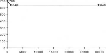
d. Pump Pressure During stages 2, 3, and 4 of the killing operation Pc2 = pk_xPd
Pm
= 10.13 x 600
9.5
= 639.8 psi
|
|
|
STANDPIPE PRESSURE |
|
NO. STROKES |
|
<? о |
|
C O N T E N T S 1. INTRODUCTION 2. COMPONENT PARTS OF A CASING STRING 3. CASING TERMINOLOGY 3.1 Conductor Casing (30” O. D.) 3.2 surface Casing (20” O. D.) 3.3 Intermediate Casing (13 3/8” O. D.) 3.4 production Casing (9 5/8” O. D.) 3.5 liner (7” O. D.) 4. properties of casing 4.1 Casing size (Outside Diameter — O. D.) 4.2 Length of Joint 4.3 Casing Weight 4.4 Casing Grade 4.5 Connections 5. api specifications, standards AND BUL letins 6. wellheads and casing hangers 6.1 spool Type Wellhead 6.2 Compact spool (speedhead) 6.3 Casing Hangers 7. RIG-siTE OpERATIONs 7.1 Handling procedures 7.2 Casing Running procedures 7.3 Casing Landing procedures 7.4 Liner Running procedures 8. casing design 8.1 Introduction to the Casing Design process 8.1.1 Design Casing Scheme Configuration — selecting Casing sizes and setting Depths 8.1.2 Define the Operational Scenarios and Consequent Loads on the Casing 8.1.3 Calculate the Loads on the Casing and select the Appropriate Weight and Grade of Casing 8.2 Casing Design Rules Base 8.3 Other design considerations 8.4 summary of Design process |

