 Running and Cementing the 30" Casing
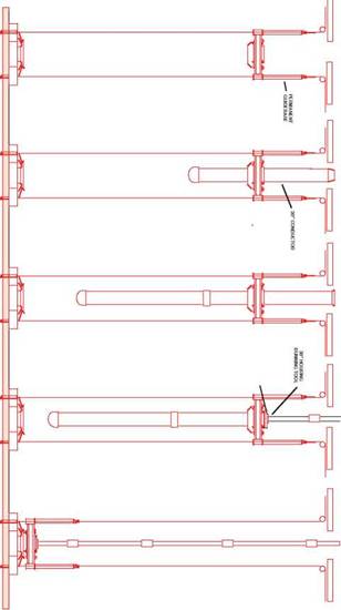
The 30” casing and casing head housing (CHH) is run to the seabed with the Permanent Guide Base — PGB. The PGB provides precise alignment for the BOP stack, and subsequently Xmas tree, over the Wellhead. The four guideposts are 12ft high and spaced at a 6ft radius around the centre of the base. A machined profile on the inside of the central slot provides support for the 30” wellhead housing and allows it to be locked in place. The PGB rests on the TGB.
The PGB is positioned in the moonpool of the rig and the guidelines are inserted into the guide posts. The 30" casing is run from the rig floor through the PGB. The top joint of casing, with the 30" casing head housing welded to it, is lowered through the rotary table, landed on the PGB and locked in place. The 30” Casing Head Housing supports the weight of the 30” casing, locks the 30” casing into the PGB and provides an internal profile onto which the 18 3/4" high pressure wellhead housing will land.
|
|
Drill pipe for cementing the casing is run down inside the casing and wellhead and made up to the underside of the 30” running tool. The 30” running tool is made up to the 30" casing housing. The Casing Head Housing running tools can be cam or rotation operated. They have drillpipe thread preparations on their upper and lower end. The upper connection is to allow the tool to be run on drillpipe and the lower is for suspending a cement stinger inside the casing. An O-ring on the outside of the running tools seal against a polished surface on the inside of the CHH preventing circulation up the annulus between the cement stinger and 30” casing.
The 30” running tool is then locked into the 30" casing and the casing string and PGB can be picked up as a single unit and run down until the PGB lands on the TGB (Figure 5). The gimbal on the underside of the PGB rests on the funnel of the TGB to give vertical alignment (checked with a the ROV viewing a bullseye indicator on the PGB). The casing is cemented by circulating down the drill pipe and out through the casing shoe until cement returns are observed, on a TV camera, to be coming up between the TGB and the PGB, and spilling onto the seabed. The volume of cement used is generally 100% in excess of the gauge hole annular volume. The cement is then displaced to just above the shoe, the running tool released from the 30" housing and the tool and drill pipe retrieved. The 30" casing is a major load bearing element in the wellhead system and it is essential that the 30" is cemented all the way up to the seabed. If cement is not observed at the seabed a top-up cementation, via a stinger through the PGB, will generally be performed.
Although many companies do use them as standard it is not always necessary to use a TGB. Indeed in soft conditions the TGB may sink into the seabed or settle unevenly. It is possible to drill the 36" hole and run the 30" casing without the help of a TGB. In this case the guidelines are attached to the guideposts of the PGB. Before cementing the 30" casing however, it is important to check that the slope of the PGB is less than 1° (otherwise the BOP stack may not latch properly).
In the case of a very soft seabed the 30" casing can be “jetted” into position. A jetting bit with a stabiliser on drill pipe is run down inside the 30" casing and suspended from the casing running tool. The jetting bit should be spaced out such that it lies about 2ft. from the open-ended shoe joint. The 30" housing is locked onto the PGB and the running tool made up as before. The whole assembly is then lowered to the seabed. Sea water is pumped through the jetting assembly to wash away the formation (holes in the running tool allow the water to escape from the drill pipe/casing annulus and spill onto the seabed). The casing is lowered slowly, as jetting continues, until the PGB is a few feet from the mudline. The jetting is stopped, the running tool released and the drill pipe is retrieved.
1.4 Installation of the Diverter
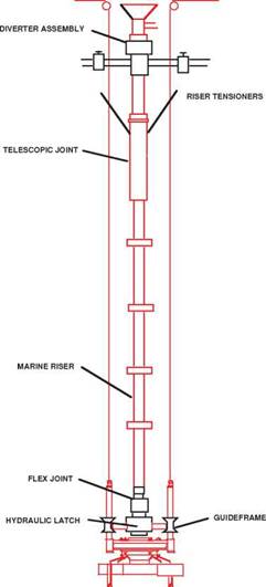
The 26" hole will generally be drilled with seawater to 1000-2000 ft. In most cases this hole section is drilled without circulation back to the rig and in this case the drilled cuttings are deposited on the seabed. If however, the drill bit encounters an unexpected gas pocket (shallow gas) there will be no blowout protection in place. For exploration wells therefore, a riser and diverter system is normally installed prior to commencing the 26" hole. The riser and diverter system is comprised of 4 basic pieces of equipment (Figure 6) :
(i) A hydraulic latch to provide a sealed interface between the 30" casing housing and the riser.
|
<? |
(ii) A flexible joint to allow some deflection of the riser (about 10°).
(iii) A marine riser to provide a conduit for returns to the rig.
(iv) A flow diverter to safely vent off any gas that may be encountered.
|
□ С
Figure 6 Installing the Diverter |
Due to the I. D. restrictions of the hydraulic latch and riser a 26" bit cannot be run through a diverter system. The 26” hole is therefore drilled by first drilling a small diameter (12 1/4") pilot hole, logging the open formations, removing the diverter assembly and then opening out to 26" diameter. The logging operation is performed to ensure that there are no open hydrocarbon bearing sands in the pilot hole section prior to removal of the diverter assembly. Alternatively the 26” hole is drilled by drilling a small diameter (12 1/4") pilot hole, logging and then running an underreamer down through the diverter assembly to open the hole out to 26”. The diverter assembly will however still have to be removed before running the 18 5/8” casing.

