 Shock Load
|
|
When casing is being run into the hole it is subjected to acceleration loading by setting of the slips and the application of hoisting brakes. Unlike the suspended weight of the pipe and the bending force, the accelerating or shock load acts on a certain part of the pipe for only a short period of time. However, the combined effects of shock load, suspended weight and bending force can lead to parting of the pipe. The effect of shock load on drillpipe was first recognized by Vreeland (1961) and a systematic procedure for determining the shock load during the running of casing strings in the hole was later presented by Rabia (1987).
|
|
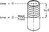
Fig. 2.5 : Effect of shock load on pipe body. (After Vreeland, 1961.)
When, during the running of casing, the string is stopped suddenly in the slips, a compressive stress wave is generated in the pipe body near the slips (Fig. 2.5). which travels downwards from the slip area towards the casing shoe. On reaching the unrestrained shoe, the compressive stress-wave is reflected upwards towards the surface as a tensile stress-wave. Arriving back at the surface, the reflected tensile stress-wave encounters the fixed end held in the slips whereupon it is reflected back downwards towards the casing shoe as a tensile stress-wave. At the free end (shoe), the two opposite stress waves cancel each other, whereas at the fixed end (slips) the two tensile stress-waves, one moving upwards and the other moving downwards and of opposite sign, combine to produce a stress equal
to twice the tensile stress (Coates, 1970).
Consider that the casing string is moving downwards at a speed of Vp when its downward motion is arrested by the setting of the slips. The particles in the pipe body continue to move at a velocity Vp. thereby inducing a stress wave to propagate downwards from the slips at a velocity VC After a time fi has elapsed, the wave will have travelled a distance VSQ. During the same time, the particles in the pipe body travel a distance VpCl.
Applying the Law of Conservation of Momentum, the change in momentum of the pipe element, can be given by:
mVp = Impulsive force x time
{asAs) П
where:
m = mass of the pipe section VSQ. i. e.. VSQ.4* "ys/g. lb.
Vs — velocity of the stress wave, ft/s.
= characteristic wave velocity for steel is 17.028 ft/s.
Vp — velocity of particles in pipe, ft/s.
us = compressive stress resulting from the action of the slips, psi.
|
|
Rewriting Eq. 2.45:
(2.46)
which after cancelling yields:
Net stress is twice the stress induced by the slip action and, therefore, the total shock load can be expressed by:
|
(2.48) |
Fs = (2crs) As
or
|
(2.49) |
2 7s Vp К As Fs =——-
9
Expressing Eq. 2.49 in field units yields:
|
(2.50) |
Fs = 3,200 Wn
|
where: |
|
|
F. = |
shock load, lbf. |
|
Vs = |
17,028 ft/s. |
|
к = |
3.04 ft/s for 40 ft of casing |
|
7s = |
489.5 lb/ft3. |
|
g = |
32.174 ft/s./s. |
|
As = |
Wn/3.46 in2 (Wn in lb/ft). |
The peak running speed is about twice the average running speed because initially the casing is at rest; so Rabia (1987) suggested using a factor of two in Eq. ‘2.49.
Consider sections of N-80, 47 lb/ft casing being run into the borehole at an average rate of 9 seconds per 40 ft. Calculate the total shock load if the casing is moving at its peak velocity when the slips are set.
Equation 2.50 is based on the premise that Vp is 3.04 ft/s, i. e., 13s per 40 ft. In this example the rate is 9s per 40 ft. thus:
FS1 = 3,200 x 47 x = 217,250 lbf
Alternatively using Eq. 2.49:
|
40 , x [ — | x 17 028 x |
|
47 346 |
_ /2 x 489.5
52 = V 32.17 = ‘217,250 lbf
From Rabia (1987), recall that the peak running speed is twice the average, so the shock load is:
Fsp= 2 X ‘217,250 = 434,500 lbf

