 Suspended Weight
The weight of pipe in air is computed by multiplying its nominal weight, Vl’„ (lb/ft), by the total length of the pipe. However, when the pipe is immersed in drilling fluid, its weight is reduced due to buoyancy force which is equal to the weight of the drilling fluid displaced by the pipe body (Archimedes’ Principle). Buoyancy force acts on the entire pipe and reduces the suspended weight of the pipe. It is, therefore, important to account for the buoyancy force in calculating the weight of the pipe. Thus, the effective or buoyant weight of pipe. Fa. can be expressed as follows:
where:
Fair = weight of the string in air, lbf.
Fbu = buoyancy force, lbf.
Fa — resultant axial force, lbf.
The above equation can be rewritten as:
Fa lAsls
‘Ym)
= 1АяЪ( 1- —
|
(2.14) |
V 7s = Ta! r(l-^i
Is
Fa = FairBF (2-15)
where:
BF =
Is
7s = specific weight0 of steel. 65.4 lb/gal. 7m = specific weight of drilling fluid, lb/gal. BF — buoyancy factor
The buoyancy of the casing string is the same in any position. However, when it is vertical the entire force is concentrated at the lower end. whereas in the horizontal position it is distributed evenly over the length. At positions between horizontal and vertical, the force is a mix of concentrated and distributed.
It could be argued that buoyancy is a distributed force even in the vertical case and, therefore, reduces the weight of each increment of the pipe by the weight of the fluid displaced by that increment. However, this argument is incorrect.
Static fluids can only exert a force in a direction normal to a surface. For a vertical pipe, the only area that a fluid pressure could push upwards is the crosssection at the bottom. Thus, the buoyancy force must be concentrated at the bottom face of the pipe.
°The relationship between specific weight 7 in lb/gal (ppg) and pressure (weight) gradient, Gp , in lbf/in.2ft (psi/ft), is Gp — 0.052 x 7.
Equation 2.15 is valid only when the casing is immersed in drilling fluid, i. e., the fluid specific weight inside and outside the string is the same. During cementing operations the drilling fluid inside the casing is progressively displaced by higher specific weight cement, thereby reducing the buoyancy factor and increasing the casing hanging weight. As the cementing operation progresses, the cement flows up the outside of the casing continuing to displace the lower specific weight drilling fluid. As the cement moves up the outside of the casing the buoyancy force increases resulting in a lowering of the hanging weight.
Similarly, casing is exposed to high specific weight drilling fluid from the inside when drilling deeper sections of the well. As a result of this, the buoyancy force increases and the effective casing weight decreases. The buoyancy force under these conditions can be expressed (Lubinski, 1951) as:
Buoyant weight per unit length = downward forces — upward forces
— (Wn + GPtAt) — GPoA0 (2-16)
where:
GPt = pressure gradient of the fluid inside the casing, psi/ft.
GPo = pressure gradient of the fluid in the annulus, psi/ft.
A, = area corresponding to the casing ID, in.2
A0 = area corresponding to the casing OD, in.2
Consider a 6,000-ft section of N-80, 47 lb/ft. 9| in. casing under the following conditions across its entire length: (i) suspended in air. (ii) immersed in 9.8 lb/gal mud, (iii) 12 lb/gal cement inside and 9.8 lb/gal mud outside, (iv) 9.8 lb/gal mud inside and 12 lb/gal cement outside.
(i) The weight in air, Eai>, is given by:
FaiT = Wnl = 47 x 6,000 = 282,000 lbf
(ii) The effective weight is given by Eq. 2.15. Thus, by calculating the buoyancy factor, BF, from Eq. 2.16:
|
|
= 0.85 one obtains:
Fa = 282,000 x 0.85 = 239,807 lbf
(iii) The buoyant weight, Fa. is given by Eq. ‘2.17. First, calculating the crosssectional areas of the casing:
|
4 |
Then:
Fa = {(47 +[12 x 0.052] 27.272) — 30.238 (9.8 x 0.052)} 6.000 = 291,650 lbf
(iv) As in (iii) above:
Fa = {(47 + [9.8 x 0.052] 27.2722) — 30.238(12 x 0.052)}6,000 = 252,180 lbf
Note in particular that the maximum effective weight of the string is not Falr, the weight in air, but rather the condition given in part (iii) when the casing is filled with cement and surrounded by low specific weight mud, i. e., Fa > Fatr when GPt At > GPo A0
|
|
|
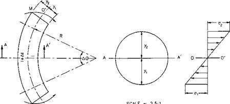
Fig. 2.3 : Pure bending of a circular beam. NOTE: y = уг — d0/2 of the beam. 2.1.2 Bending Force |
|
SCALE = 2.5:1 |
|
м 0 |
Casing is subjected to bending forces when run in deviated wells. As a result of bending, the upper surface of the pipe stretches and is in tension, whereas
the lower surface shortens and is in compression. Stress distribution across a cylindrical pipe body under bending force is illustrated in Fig. ‘2.3. Between the stretched and compressed surfaces, there exists a neutral plane 00′ in which the longitudinal deformation is zero. Thus, the deformation at the outer portion of the pipe, Ae2, can be expressed as follows:
A (/ + Д/)-/
^ = p (2.17)
Al
= — г C2-18)
where:
Al = (R + y2) A0 — R ДО = i/j A© (2.19)
= axial deformation.
I — section of the pipe length.
R = radius of curvature.
0 = angle subtended by the pipe section.
Д0 = angular deformation. y-2 — axial deformation above 00′ plane.
If the pipe remains elastic after bending, then the equation for longitudinal strain can be expressed as:
А/ A (7-2 . .
|
|
where:
E = modulus of elasticity, 30 x 106 psi.
A<72 = incremental bending stress.
Combining Eqs. 2.19 and ‘2.21, and converting into field units by expressing 0 in
radians per 100 ft of pipe, y2 in inches and As in square inches, one obtains the
equation for bending force, Ft,:
Fb — AsAa2
= А. Е-Ш — 0
12 100 180
Considering y = y2 = d0/2 and the nominal weight, of the pipe, VEn. to be equal to 3.46 Asb, then Eq. ‘2.22 can be simplified to:
|
(2.23) |
Fh = 2.10 x КГ6 Ed„Q
|
(2.24) |
or
Fb = 63 daWn 0
where:
d0 = nominal diameter of the pipe. in.
As = pipe cross-sectional area, in.2
0 = degrees (°) per 100 feet (‘dogleg severity’).
Wn — nominal weight of pipe, lb/ft.
Calculate the axial load due to bending in the string in Example 2-4 given that the maximum ‘dogleg severity’, 0, is 3°/100 ft.
Applying Eq. 2.24 one obtains:
Fb = 63 x 9.625 x 47 x 3 = 85,500 lbf
Equation 2.24, recommended by Bowers (1955), Greenip (1978). and Rabia (1987), is widely used to determine axial load due to pipe bending. The equation should, however, only be used in circumstances where the pipe is in continuous contact with the borehole.
In practice, the casing cannot be in continuous contact with the borehole because the borehole is always irregularly shaped and the casing is often run in the hole with protectors and centralizers. If the pipe is supported at two points, due to the hole irregularities or the use of centralizers. the radius of curvature of the pipe is not constant. In this case, the maximal axial stress is significantly greater than that predicted by Eq. ‘2.24.
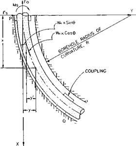
If a pipe section of length l}, supported at points P and Q subtends an angle 9 at the center of curvature (Fig. 2.4). which does not exceed its elastic limit.
4For most casing sizes, the cross-sectional area is related to nominal weight per foot, with negligible error (Goins et ah, 1965, 1966), through the relation: A = W„/3.46 in.2.
|
Fig. 2.4: Bending of casing supported at casing collars. |
|
|
classical deflection theory can be applied to determine the resultant axial stress (Lubinski, 1961). In this case the radius of curvature of the pipe is given by:
|
M_ ITl |
|
1 _ R ” where: |
|
(2.25) |
/ = moment of inertia, in.4 M = bending moment, ft-lbf
|
(2.26) |
For a circular pipe, I is expressed as:
where:
d0 = outside diameter of the pipe. in. di = inside diameter of the pipe. in.
If the curvature of the bent section is small then the radius of curvature can be given by:
— = A,2.27)
R dx2 ‘ ;
Combining Eqs. ‘2.25 and ‘2.27 one obtains:
Д " (2.28)
dx2 El У
From Fig. ‘2.4, the bending moment Mx at any distance x (where x < the joint
length) is given by:
Mx = Ms + Fay + Fwx — Wn sin 0 — Wn x y’ cos в • (2.29)
where:
Fa — axial force, lbf.
Fw = force exerted by the borehole wall at the couplings, lbf.
Ms = bending moment at 0, ft-lbf. у and y’ = refer to Fig 2.4.
The last two terms of Eq. ‘2.29 are small and for simplicity they are neglected. Similarly, the axial tension, Fa, is considered to be constant throughout the pipe. Thus, substituting Eqs. 2.21 and ‘2.28 into Eq. 2.29 and simplifying, one obtains
the classical differential equation for a beam column (Timoshenko et al.. 1961):
—L _ ^21 = 2 Ao~2 i (9 30)
dx2 El ~ Ed0 El where Дсг2 is a maximum, /crmax, at y2 = d0/2.
Maximal bending force is obtained by integrating Eq. 2.30. Defining v2 as:
</>2 = — (2.31)
v El
one obtains the integral solution:
“2 A<jn
|
1 y= 71 ■ф* |
f.
|
Eda |
(coshit’s — 1) H У777 [sinh vx — ex] (2.32)
The boundary conditions for the system are:
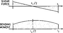
1. As there is no pipe-to-wall contact, the load on the pipe is considered to be symmetric and, therefore, the shear force at the middle of the joint is zero.
Hence,
/ x = ljJ2
where:
lj — length of a joint of casing.
2. It follows from Eq. 2.33 above, that the midpoint of the joint must be parallel to the borehole and, therefore, that the slope of the pipe is:
TOC o "1-5" h z dy I 1 ,
4.,/^
Applying the boundary conditions to Eq. 2.32 yields the following expression for the radius of curvature:
1 2 max tanh(V>/;-/2) qm
Rearranging the equation in terms of Д<JmaT, and expressing R in terms of dogleg severity, 0, one obtains:
Д<ттаг = -jj — — tanh(^/j/2) (2.36)
Similarly the bending force, Fb, is given by:
Fb = AsAo-maz (2.37)
= EdoQ tk 1 (2 m
21 j 2 tanh(t/j/j/2)
Solving for maximal stress and expressing the equation in field units:
F‘=63W"d°ekkk) {±m
Equation 2.39 was suggested by several authors: Mitchel (1990) and Bourgoyne et al. (1986); and it is being used in rating the tensional joint strength of couplings
subjected to bending. Using this equation the following formulas were developed by the API (API Bui. 5C3, 1989) to estimate the joint strength of API Round thread coupling.
The joint strength of API Round casing with combined bending and internal pressure is calculated on a total load basis.
Full fracture strength:
Fau = 0.95AJpcrup (2.40)
Jumpout and reduced fracture strength:
|
(2.41) |
0. 74do 0 59aup (1 + 0.5z)cry
Fa] = 0.95 A]PLet
0. 5Let A 0.14d0 4- 0.14dc
Bending load failure strength:
When Fab/Ajp > <rup, the joint strength is given by:
|
140.5 Qd„ |
|
(2.42) |
|
(<?up ~ <r-, ‘l0’8 |
|
‘yi |
|
Fab = 0.95 Ajp I aup |
When Fab/Ajp < crup, the joint strength is given by:
Fab = 0.95 Ajp (^~4gy + ^ — 218.15 0rfo) (2.43)
where:
Ajp = cross-sectional area of pipe wall under the last
perfect thread, in.2 = J [(rf0 — 0.1425)2 — (rf0 — 2 02] (2-44)
Fab — total tensile failure load with bending 0. lbf.
Total load = External load + sealing head load
= External load + p, A,
Pi = internal pressure, psi.
Ai — internal area, in.2
= ^(do — 2f)2 Fau — total tensile load at fracture, lbf.
z = ratio of internal pressure stress to yield strength
2ayt
Faj = minimum joint strength, lbf.
For a 40-ft length of 9| in., 47 lb/ft. X-80 casing with API long, round thread couplings subjected to a 300,000 lbf axial tension force in a section of hole with a ‘dogleg severity’ of 3°/100 ft calculate the maximal axial stress assuming; (i) uniform contact with the borehole, (ii) contact only at the couplings. In addition, compute the joint strength of the casing.
From Examples 2-1 and 2-2 the nominal values for pipe body yield strength. 1,086 x 103 lbf, and nominal joint strength. 905 x 103 lbf. were calculated.
The cross-sectional area of the pipe is given by:
As — — (9.6252 — 8.6812) = 13.5725 sq. in.
Without bending, the axial stress is given by:
300,0 TOC o "1-5" h z .
a„ = ———- = 22,104 psi
a 13.572 ’ F
The additional stress due to bending is:
(i) From Eq. 2.24, which assumes that the pipe is in uniform contact with the borehole:
л Fb 63 x 9.625 x 47 x 3 .
Дсг-2 = — = ———————— = 6.400psi
2 13.5725 F
Thus, the total stress in the pipe is:
<re + Дсг2 = 22,104 + 6,400 = 28,504 psi a 29% increase in stress due to bending.
(ii) From Eq. 2.39, which assumes that contact between the casing and the borehole is limited to the couplings. First from Eq. 2.26:
I = — (9.6254 — 8.6814) = 142.51 in.4 64 ^ ‘
|
, .-a . 300,000 ф = |
Similarly, from Eq. 2.31:
Thus,
|
A(Tmax, A. |
’64 x 9.625 x 47 x 3 / 6 x (8.377 x 1СГ3) x 40
13.5725 / _tanh(6 x 8.377 x 10-3 x 40)
= 13,337 psi
Thus, the total stress in the pipe is:
era + Aamax = 22,104 + 13,337 = 35.441 psi
A 60 % increase in stress due to bending. Note that in the second case the
additional stress due to bending is more than double that calculated assuming
uniform contact with the borehole.
In this example both methods produce maximal axial stresses well below the
80,0 psi minimal yield stress of N-80 grade casing.
(iii) The minimal ultimate yield strength of N-80 grade casing is aup — 100,000 psi, so using Eq. 2.42 one obtains the value for joint strength:
Fab _ Л ( 140.5 x 3 x 9.625 4 5N
-P — = 0.95 x 100,000 — . ,
AjP V(l°0-000 — 80.000)0-8,
= 94,993 psi
Inasmuch as Fab/Ajp > 80,000, the above value for joint strength is valid and there is no need to apply Eq. 2.43.
Similarly, the cross-sectional area of pipe wall under the last perfect thread. AJP, is:
Ajp = “{(9.625 — 0.1425)2 — (9.625 — 2(0.472))2}
= 11.434 sq. in.
and the calculated joint strength is:
Fab = 94,993 x 11.434 = 1,086.150 lbf
This value is above the nominal joint strength value of 905 x 103 lbf given in the tables and so the nominal table value must instead be based on joint pull-out strength. Thus, under the given conditions joint strength is determined by the minimal pull-out force.


