 BLOWOUT PREVENTION (BOP) EQUIPMENT
The blowout prevention (BOP) equipment is the equipment which is used to shut — in a well and circulate out an influx if it occurs. The main components of this equipment are the blowout preventers or BOP’s. these are valves which can be used to close off the well at surface. In addition to the BOP’s the BOP equipment refers to the auxiliary equipment required to control the flow of the formation fluids and circulate the kick out safely.
There are 2 basic types of blowout preventer used for closing in a well:
• Annular (bag type) or
• Ram type.
It is very rare for only one blowout preventer to be used on a well. Two, three or more preventers are generally stacked up, one on top of the other to make up a BOP stack. This provides greater safety and flexibility in the well control operation. For example: the additional BOPs provide redundancy should one piece of equipment fail; and the different types of ram (see below) provide the capability to close the well whether there is drillpipe in the well or not. When drilling from a floating vessel the BoP stack design is further complicated and will be dealt with later.
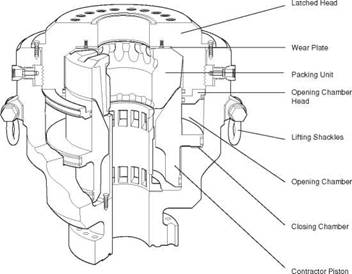
the main component of the annular BoP (Figure 18) is a high tensile strength, circular rubber packing unit. the rubber is moulded around a series of metal ribs. the packing unit can be compressed inwards against drillpipe by a piston, operated by hydraulic power.
the advantage of such a well control device is that the packing element will close off around any size or shape of pipe. An annular preventer will also allow pipe to be stripped in (run into the well whilst containing annulus pressure) and out and rotated, although its service life is much reduced by these operations. the rubber packing element should be frequently inspected for wear and is easily replaced.
The annular preventer provides an effective pressure seal (2000 or 5000 psi) and is usually the first BOP to be used when closing in a well (Figure 19). The closing mechanism is described in Figure 20.
|
Figure 19 Annular type BOP (Courtesy of Hydril*) |
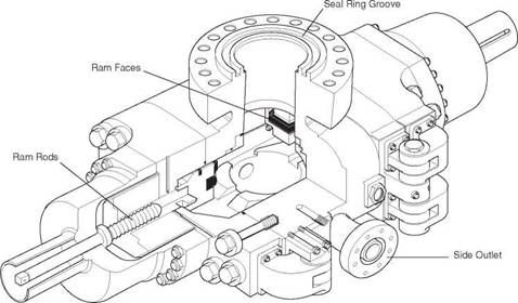
Ram type preventers (Figure 22) derive their name from the twin ram elements which make up their closing mechanism. Three types of ram preventers are available:
%
|
|
|
|
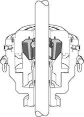
Annular preventers seal off the annulus between the drilstring and BOP stack. During normal well-bore operations, the BOP is kept fully open by holding the contractor piston down. This position permits passage of tools, casing and other items up to the full bore size of the BOP as well as providing maximum annulus flow of drilling fluids. The BOP is maintained in the open position by application of hydraulic pressure to the opening chamber, this ensures positive control of the piston during drilling and reduces wear caused by vibration.
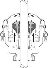
The contractor piston is raised by applying hydraulic pressure to the closing chamber. This raises the piston, which in turn squeezes the steel reinforced packing unit inward to seal the annulus around the drill string. The closing pressure should be regulated with a separate pressure regulator valve for the annular BOP.
|
|
|
|
The packing unit is kept in compression throughout the sealing area thus assuring a tough, durable seal off against virtually any drill string shape, kelly, tool joint, pipe or tubing to full rated working pressure Application of opening chamber pressure returns the piston to the full down position allowing the packing unit to return to full open bore through the natural resiliency of the rubber.
Figure 20 Details of closing mechanism on an annular preventer (Courtesy of Hydril[3])
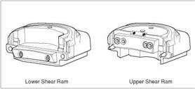
The sealing elements are again constructed in a high tensile strength rubber and are designed to withstand very high pressures. the elements shown in Figure 21 are easily replaced and the overall construction is shown in Figure 22. Pipe ram elements must be changed to fit around the particular size of pipe in the hole. To reduce the size of a BOP stack two rams can be fitted inside a single body. The weight of the drillstring can be suspended from the closed pipe rams if necessary.
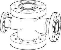
A drilling spool is a connector which allows choke and kill lines to be attached to the BOP stack. The spool must have a bore at least equal to the maximum bore of the uppermost casing spool. the spool must also be capable of withstanding the same pressures as the rest of the BoP stack (Figure 23). these days outlets for connection of choke and kill lines have been added to the BoP ram body (Figure 22) and drilling spools are less frequently used. These outlets save space and reduce the number of connections and therefore potential leak paths.
|
|
|
|
|
|
|
|
|
Figure 21 types of ram elements (courtesy of Hydril*) |
|
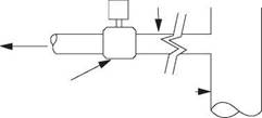
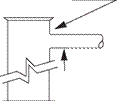
The diverter is a large, low pressure, annular preventer equipped with large bore discharge flowlines. This type of BOP is generally used when drilling at shallow depths below the conductor. If the well were to kick at this shallow depth, closing in and attempting to contain the downhole pressure would probably result in the formations below the conductor fracturing and cratering of the site or at least hydrocarbons coming to surface outside of the conductor string. the purpose of a diverter is to allow the well to flow to surface safely, where it can be expelled safely expelled through a pipeline leading away from the rig. The kick must be diverted |
the wellhead, from which the casing strings are suspended are made up of casing spools. A casing spool will be installed after each casing string has been set. the BOP stack is placed on top of the casing spool and connected to it by flanged, welded or threaded connections. once again the casing spool must be rated to the same pressure as the rest of the BoP stack. the casing spool outlets should only be used for the connection of the choke and/or kill lines in an emergency.
%
|
X |
safely away from the rig through the large bore flowlines. The pressure from such a kick is likely to be low (500 psi), but high volumes of fluid can be expected. The diverter should have a large outlet with one full opening valve. the discharge line should be as straight as possible and firmly secured. Examples of diverter systems are given in API RP 53.
|
Figure 22 Details of ram preventer (courtesy of Hydril*) |
When circulating out a kick the heavy fluid is pumped down the drillstring, up the annulus and out to surface. Since the well is closed in at the annular preventer the wellbore fluids leave the annulus through the side outlet below the BOP rams or the drilling spool outlets and pass into a high pressure line known as the choke line. The choke line carries the mud and influx from the BOP stack to the choke manifold. the kill line is a high pressure pipeline between the side outlet, opposite the choke line outlet, on the BoP stack and the mud pumps and provides a means of pumping fluids downhole when the normal method of circulating down the drillstring is not possible.
|
Figure 23 Flanged drilling spool |
The choke manifold is an arrangement of valves, pipelines and chokes designed to control the flow from the annulus of the well during a well killing operation. It must be capable of:
• Controlling pressures by using manually operated chokes or chokes operated from a remote location.
• Diverting flow to a burning pit, flare or mud pits.
• Having enough back up lines should any part of the manifold fail.
• A working pressure equal to the BOP stack.
|
Full — opening valve (Automatically opens when diverter closes) |
|
Diverter — |
|
Diverter line |
|
Drive pipe or — conductor pipe |
|
Figure 24 Diverter System |
|
|
|
Vent line should be correctly oriented downwind from the rig and facilities |
Since, during a gas kick, excessive vibration may occur it must be well secured.
|
Bell/Flow nipple
Flow line |
X
%
A choke is simply a device which applies some resistance to flow. The resistance creates a back pressure which is used to control bottomhole pressure during a well killing operation. Both fixed chokes and adjustable chokes are available (Figure 25). the choke can be operated hydraulically or manually if necessary.
