 BOP STACK ARRANGEMENTS
The individual annular and ram type blowout preventers are stacked up, one on top of the other, to form a BOP stack. The configuration of these components and the associated choke and kill lines depends on the operational conditions and the operational flexibility that is required.
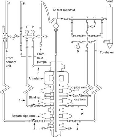
The placement of the elements of a BOP stack (both rams and circulation lines) involves a degree of judgement, and eventually compromise. However, the placement of the rams and the choke and kill line configuration should be carefully considered if optimum flexibility is to be maintained. Although there is no single optimum stack configuration, consider the configuration of the rams and choke and kill lines in the BOP stack shown in Figure 27:
• There is a choke and kill line below each pipe ram to allow well killing with either ram.
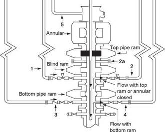
• Either set of pipe rams can be used to kill the well in a normal kill operation (Figure 28).
• If there is a failure in the surface pumping equipment at the drillfloor the string can be hung off the lower pipe rams, the blind rams closed and a kill operation can be conducted through the kill line (Figure 29).
• If the hydril fails the pipe can be stripped into the well using the pipe rams. In this operation the pipe is run in hole through the pipe rams. With the pressure on the pipe rams being sufficient to contain the pressure in the well. When a tooljoint reaches the upper pipe ram the upper ram is opened and the tooljoint allowed to pass. The upper pipe ram is then closed and the lower opened to allow the tooljoint to pass (Figure 30). This operation is known as ram to ram stripping.
%
|
X |
this arrangement is shown as an illustration of considerations and compromise and should not be considered as a ‘standard’.
the placement of the choke and kill lines is also a very important consideration when designing the stackup. Ideally these lines are never made up below the bottom ram. However, compromise may be necessary.
the following general observations can be made about the arrangement detailed in Figure 27:
1. No drilling spools are used. this minimises the number of connections and chances of flange leaks.
2. the double ram is placed on top of a single ram unit. this will probably provide sufficient room so that the pipe may be sheared and the tool joint still be held in the lower pipe ram.
|
Figure 27 BoP Stack and choke and kill line arrangement |
3. Check valves are located in each of the kill wing valve assemblies. this will stop flow if the kill line ruptures under high pressure killing operations.
4. Inboard valves adjacent to the BOP stack on all flowlines are manually operated ‘master’ valves to be used only for emergency. Outboard valves should be used for normal killing operations. Hydraulic operators are generally installed on the primary (lines 1 and 2) choke and kill flowline outboard valves. This allows remote control during killing operations.
5. No choke or kill flowlines are connected to the casing-head outlets, but valves and unions are installed for emergency use only. It is not good practise to flow into or out of a casing head outlet. If this connection is ruptured or cutout, there is no control. Primary and secondary flowlines should all be connected to heavy duty BOP outlets or spools.
|
closed Figure 28 Normal kill operation |

