 Calculations for Inclination, Toolface and Azimuth
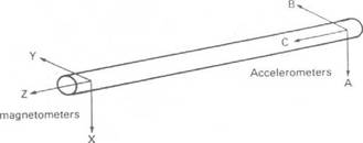
In the following equations a, b, c, x, y, z refer to the accelerometer and magnetometer readings with axes as shown in Figure 3.
Inclination (a) — the angle between C accelerometer and vertical. Looking at a verticalion cross-section
|
Figure 3 Orientation of Sensors in Tool |
|
a = tan |
a2 + b2
Equation 1 Inclination of Tool
Toolface (b) — the angle between high side and B accelerometer. Looking down the tool along the C axis:
|
(a? v bj |
|
-i |
в = tan
Equation 2 Toolface of Tool
(Note: This gives the toolface of the MWD tool itself. To measure the toolface of the bent sub the offset angle must be included).
Azimuth (0) — the angle between the Z axis and magnetic North, when projected on to the horizontal plane. Looking in the horizontal plane we define 2 vectors V1 and V2 where V1 lies along tool axis.
V1 = z sina + x cosa sinb + y cosb cosa
V = x cosb — y sinb
в = tan -1
1
|
|
and substituting for a, b
Г c(xb + yb) + z (a2 = b2)
в = tan 1 ——————— —————————
g(xb — ya)
Equation 3 Azimuth of Tool
(Note: this gives Magnetic azimuth, not True azimuth)
Notice that accelerometer readings are also used in the calculation of azimuth. If there is any mistake in the accelerometer readings, therefore, inclination, toolface and azimuth will all be wrong. Since we are relying on the magnetometers responding only to the earth’s magnetic field any local magnetic effects from the drillstring must be isolated. There must be enough non-magnetic drill collars above and below the sensors to stop any such interference. As a result of this the sensors will be operating 40′ — 80′ behind the bit (the exact distance must be known before the tool
is run).
|
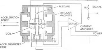
CAPACITIVE PICKOFF Figure 4 Accelrometer |
The usual practice in taking a survey is to drill to kelly down and make the connection. Run in the hole and tag bottom. Pick up 5′-10′ and keep pipe steady for 2 minutes (this allows survey data to be stored). Re-start drilling and survey data is transmitted to surface. In some tools the transmission is initiated by rotation, in others it senses pump pressure. During a steering run where a mud motor is being used an update of toolface is usually transmitted every minute. This is of great value to the directional driller as he monitors the progress of the well.
MWD companies quote slightly different figures for accuracy but generally within the following limits:
Inclination Azimuth Toolface
+/- 0.25o +/- 1.50o +/- 3.00o
|
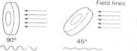
Figure 5 Magnetometer |
These figures compare favourably with single shot accuracies and MWD offers the advantage of being able to repeat surveys at the same depth with little loss in rig time
0°


