 Example systems
|
. The |
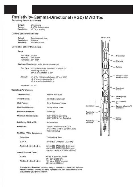
A typical Resistivity-Gamma-Directional MWD Tool is shown in Figure specifications of this tool configuration are also presented.
|
Figure 8 Typical MWD Tool Configuration |
|
INTRODUCTION 1. DRILLING THE WELL
|
2. COMPLETING THE WELL
2.1 Installing the tubing string and tubing hanger
2.2 Removal of the BOP STAck and Installation of the Xmas Tree.
2.3 Cleaning up the well
3 suspending the WELL
4. abandonment
|
<? CD |
|
% |
• Describe the subsea BOP and riser equipment used to drill from a floating drilling vessel
• Decribe the guide base and wellhead equipment used to drill a subsea well from a floating vessel
• Describe the steps involved in the process of drilling a subsea well.
The operations and equipment used to drill a well from a production platform are almost identical to those used for a land well. A conductor is driven into the seabed and the hole sections are drilled through wellhead and BOP equipment which is similar to that used on land locations. The wellhead and BOP are located on the lower deck of the platform. When the well has been drilled and completed the Xmas tree (which is also similar to that used on land locations) is mounted on top of the wellhead.
The type of wellhead and blowout prevention equipment used when drilling a well from a mobile drilling rig will be quite different from that used on a platform based operation. The equipment used in this case will depend on whether the operation is being conducted from a floating drilling vessel (drillship or Semi-submersible) or from a stable, Jackup drilling vessel. The vessel used will in turn depend largely on whether the well is an exploration or development well and the water depth in which it is being drilled.
When drilling from a Jackup, the drilling operations are very similar to platform — based or land-based operations with a conductor being driven into the seabed and conventional wellhead and surface BOP stack equipment being used. However, since the Jackup will have to move off location when the drilling operation is complete the casing strings must be physically supported at the seabed and it must be possible to remotely disconnect the casing strings between the seabed and surface when the operation is complete. The only alternative to this seabed support is to leave a ‘freestanding’ conductor on location but in most areas this is not a feasible alternative. Seabed support for such wells is provided by a Mudline suspension (MLS) system. The MLS system is a series of full bore housings and hangers run with the casing strings and is discussed fully, later in this chapter.
When drilling with an MLS system the casing strings are temporarily extended back from the mudline to surface and the conventional wellhead and BOP stack is nippled up on top of these extension strings (just beneath the rigfloor). The MLS system only provides physical support for the casing strings. All annulus sealing and monitoring functions are provided by the wellhead at surface.
When the well has been drilled it is possible to convert the MLS system into a subsea wellhead, such that the well can be completed subsea, although this is not a typical application of MLS technology. These systems are generally used on development drilling operations, where a platform is to be used for production purposes. The operation is conducted as follows: a Jackup drilling unit and MLS system is used to drill the wells; the wells are suspended and the tieback strings removed; and the rig is moved away from the location. When the platform is complete it is installed over the location and the wells are re-entered and re-connected, with extension strings, to the lower deck of the platform and a conventional wellhead and Xmas tree system is installed on top of the extension (tie-back) strings. This is known as a ‘pre-drilling’ operation.
|
|
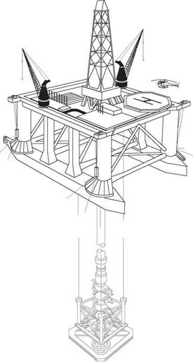
When drilling from a floating vessel drillship or Semi-submersible (Figure 1) there is always the possibility that, at some point during the drilling operation, the vessel will have to disconnect from the well or even move off location due to bad weather. The wellhead and all other BOP equipment are therefore situated on the seabed with the drilling fluids being circulated back to the drilling vessel via a marine riser. The BOP stack on the seabed is the primary well control device, in the event of a kick. A hydraulic latch between the marine riser and the BOP stack ensures that it is possible to close in the well, disconnect the marine riser from the top of the BOP stack and move the rig off location safely at any stage during the drilling operation. When the well has been drilled and the well is either suspended for later completion or it may be completed immediately and a subsea Xmas tree installed on the wellhead. We will assume that the well is to be completed immediately after the drilling operations are complete.
|
Figure 1 Semi-Submersible Drilling Rig |
The first part of this chapter will outline the operations and equipment used when drilling and completing a well from a floating vessel, using a subsea wellhead
system. A description of the operations involved in drilling from a Jackup, using an MLS system is given in the next chapter. For continuity purposes, the casing scheme used as the basis for discussion in this chapter will be : 30”, 18 5/8”, 13 3/8”, 9 5/8” and 7” (Figure 2). It is worth noting that all manufacturers use the same basic principles, although there are certain differences in the design and operation of some components.
|
Figure 2 Casing Configuration |
There are two types of guidance system which can be used to run subsea wellhead equipment to the seabed when drilling from a Drillship or Semi-Submersible — a guideline and guidelineless system. The choice of system will depend on water depth. In water depths of less than 1500 ft this equipment is run and retrieved using wire rope guidelines anchored at the seabed. In the case of very deep water (>1500ft) it is necessary to use techniques which allow the equipment to be run and retrieved remotely without the use of divers or fixed guidelines (guidelineless system). The more common guideline system will be described in this chapter. The description relates to those operations performed when using a VETCO wellhead system.


