 Exercise 3 Hydraulics Optimisation
1. a. Calculate Maximum Flowrate
b. Determine Minimum Flowrate
c. Calculate Maximum Surface Pressure
a. Calculate the maximum volume output by each liner size and therefore the maximum flowrate:
q _ d2LxEv xR Q _ 98.03
|
d = |
5 3/4", 6 1/2", 7" |
||
|
l = |
12" |
||
|
Ev = |
0.95 |
||
|
R = |
120 spm |
||
|
d |
Q |
P max. |
Ann. Velocity |
|
in. |
gpm |
psi |
ft/min. |
|
5 3/4" |
461 |
5354 |
90 |
|
6 1/2" |
590 |
4183 |
116 |
|
7" |
684 |
3614 |
134 |
Note : Pmax. is calculated on the basis of :
PxQ
HHPt x Em =
Note: Ann. Velo. is based on 5" d. p. in 12 1/4" hole (+/- 5.1 gal./ft.)
b. The minimum annular velocity will be that required to ensure that the cuttings are removed from the hole. A typical value would be 110 ft/min. The 6 1/2" liner would therefore be selected and the maximum flowrate would be 590 gpm.
c. As shown above the maximum surface pressure would be 4183 psi at 590 gpm.
2. The pump pressures for four different pump rates were recorded prior to pulling the previous bit from the hole. They were as follows :
|
Pump Rate Surface Pressure
|
|
|
the bit pressure losses can be calculated from the following
42
|
Pbit = |
|
2 |
|
bit |
P x Q2 564 A
|
p = 0.52 psi/ft An= 0.45 in2 |
|
|
Flowrate |
|
|
GPM |
psi |
|
590 |
1585 |
|
516 |
1212 |
|
443 |
894 |
|
393 |
703 |
|
where, |
|
P |
|
From the above tabulation the pressure losses in the circulation system can be
|
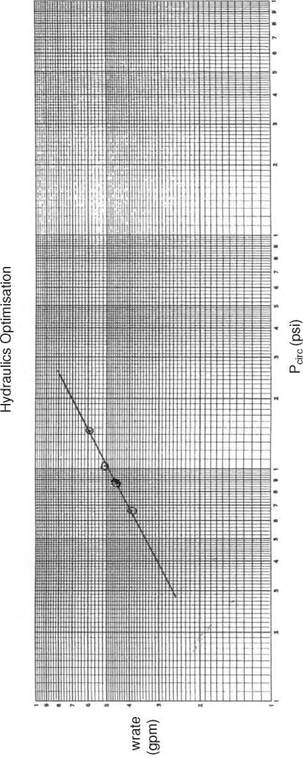
3. The flowrate is plotted against the circulating pressure loss on log-log paper (See Figure Solution 3) and the gradient of the line measured. The gradient of this line is approx. 1.85.
4. From Table 1 it can be seen that the circulating system factor W is 0.35.
5. Thus the optimum circulating pressure loss at this depth and with this system is
P. t= WxP
circ. opt max
P. = 1464 psi
circ. opt
6. If this line is plotted on the log-log plot the optimum flowrate can be deduced. The optimum flowrate is found to be 600 gpm.
|
23 75 V P — P ^ у x max a circ. opt. |
7. The optimum nozzle area is selected on the basis of the following equation : Nozzle area — Q°pt — I P
and the optimum configuration can then be selected from Table 2 as being 13/32", 12/32", 12/32".
|
о El О |
1. INTRODUCTION
2. APPLICATIONS
3. DEPTH REFERENCE AND GEOGRAPHICAL REFERENCE SYSTEMS
3.1 Depth Reference Systems
3.2 Geographical Reference Systems
4. PLANNING THE PROFILE OF THE WELL
4.1 Parameters Defining the Wellpath
4.2 Defining the Points on the Wellpath
4.2.1 Scaled Diagrams
4.2.2 Geometrical Calculation Technique
5. CONSIDERATIONS WHEN PLANNING THE DIRECTIONAL WELL PATH
6. DEFLECTION TOOLS
6.1 Bent Sub and Mud Motor
6.2 Steerable Drilling Systems
6.2.1 Components
6.2.2 Dogleg Produced by a Steerable System
6.2.3 Operation of a Steerable System
6.3 Rotary Steering System
6.3.1 Downhole System
6.3.2 Surface System
6.4 Directional Bottom Hole Assemblies (BHA)
6.4.1 Packed Hole Assembly
6.4.2 Pendulum Assembly
6.4.3 Fulcrum Assembly
6.5 Whipstocks
APPENDIX — I : Positive Displacement Motors (PDM’s) and Turbodrills
|
f Л V /A — & |
Solutions to Exercises
Having worked through this chapter the student will be able to: General:
• List and describe the applications of directional drilling techniques
• Describe the constraints on the trajectory of a deviated well.
• Define the terms: KOP; BUR; and tangent section of the well trajectory.
Trajectory Design:
• Calculate the: along hole depth, TVD and departure of the end of the build up section and the along hole depth of the bottom of the hole in a build and hold well profile.
Deflection Tools
• Describe the principles used in the deflection of a wellbore from a given trajectory.
• List and describe the tools used to initiate changes in wellbore trajectory.
• Describe the principles associated with the packed hole, pendulum and fulcrum BHA and when each would be used.
• Describe the component parts of a steerable drilling system and the mode of operation of such a system.
• Calculate the dogleg severity generated by a given BHA.
PDM’s and Turbodrills:
• Describe the principles of operation of a PDM and Turbodrill.
1. INTRODUCTION
In the early days of land drilling most wells were drilled vertically, straight down into the reservoir. Although these wells were considered to be vertical, they rarely were. Some deviation in a wellbore will always occur, due to formation effects and bending of the drillstring. The first recorded instance of a well being deliberately drilled along a deviated course was in California in 1930. This well was drilled to exploit a reservoir which was beyond the shoreline underneath the Pacific Ocean. It had been the practise to build jetties out into the ocean and build the drilling rig on the jetty. However, this became prohibitively expensive and the technique of drilling deviated wells was developed. Since then many new techniques and special tools have been introduced to control the path of the wellbore.
An operating company usually hires a directional drilling service company to: provide expertise in planning the well; supply special tools; and to provide onsite assistance when operating the tools. The operator may also hire a surveying company to measure the inclination and direction of the well as drilling proceeds.
In this chapter we will discuss: the applications of directional well drilling; the design of these wells; and the techniques used to drill a well with controlled deviation from the vertical. The next chapter will discuss the tools and techniques used to survey the position of the well (determine the three dimensional position of all points in the wellbore relative to the wellhead).
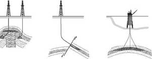
There are many reasons for drilling a non-vertical (deviated) well. Some typical applications of directionally controlled drilling are shown in Figure 1.
(a) Multi-well Platform Drilling
Multi-well Platform drilling is widely employed in the North Sea. The development of these fields is only economically feasible if it is possible to drill a large number of wells (up to 40 or 60) from one location (platform). The deviated wells are designed to intercept a reservoir over a wide aereal extent. Many oilfields (both onshore and offshore) would not be economically feasible if not for this technique.
(b) Fault Drilling
If a well is drilled across a fault the casing can be damaged by fault slippage. The potential for damaging the casing can be minimised by drilling parallel to a fault and then changing the direction of the well to cross the fault into the target.
(c) Inaccessible Locations
Vertical access to a producing zone is often obstructed by some obstacle at surface (e. g. river estuary, mountain range, city). In this case the well may be directionally drilled into the target from a rig site some distance away from the point vertically above the required point of entry into the reservoir.
|
|
(d) Sidetracking and Straightening
It is in fact quite difficult to control the angle of inclination of any well (vertical or deviated) and it may be necessary to ‘correct’ the course of the well for many reasons. For example, it may be necessary in the event of the drillpipe becoming stuck in the hole to simply drill around the stuckpipe (or fish), or plug back the well to drill to an alternative target.
(e) Salt Dome Drilling
Salt domes (called Diapirs) often form hydrocarbon traps in what were overlying reservoir rocks. In this form of trap the reservoir is located directly beneath the flank of the salt dome. To avoid potential drilling problems in the salt (e. g. severe washouts, moving salt, high pressure blocks of dolomite) a directional well can be used to drill alongside the Diapir (not vertically down through it) and then at an angle below the salt to reach the reservoir.
(f) Relief Wells
If a blow-out occurs and the rig is damaged, or destroyed, it may be possible to kill the “wild” well by drilling another directionally drilled well (relief well) to intercept or pass to within a few feet of the bottom of the “wild” well. The “wild” well is killed by circulating high density fluid down the relief well, into and up the wild well.
|
|
|
|
|
|
