 Magnetic Multi-shot
At certain points in the well it is useful to determine the overall trajectory in a single survey run (e. g. just before running casing). This is usually done by a multi-shot instrument which takes a series of pictures. A magnetic multi-shot works on the same principle as a magnetic single shot, but has a special camera unit. A roll of film is automatically exposed and wound on at pre-set intervals (Figure 12).
|
|
|
Camera |
|
Lens |
|
Motor |
|
Lights |
|
Timer |
Battery Pack
|
Compass Fluid Compass Card
Glass Cover Plumb Bob Concentric Ring Glass Figure 12 Magnetic Multishot Device |
The magnetic multi-shot is either dropped free, or lowered into the non-magnetic collar by wireline. Since the compass must remain within the non-magnetic collar to operate accurately, the multishot survey is taken as the pipe is tripped out of the hole. The directional surveyor must keep track of the depth at which the preset timer takes a picture. Only those shots taken at known depth when the pipe stationary will be recorded. When the multi-shot is recovered, the film is developed and the survey results read.
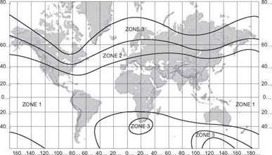
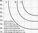
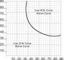
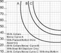
The readings from a magnetic compass will be incorrect if the compass is close to a magnetised piece of steel. Since both the drillstring and casing will be magnetised, as they are run through the earths magnetic field, the magnetic surveying tools cannot be used unless some measure is taken to ensure that the well direction according to the earths magnetic field is accurately recorded on the compass. In the case of the drillstring this is done by using non-magnetic drillcollars in the BHA. These collars are made from Monel and the Earths magnetic field is undisturbed by their presence. An accurate reading of the direction of the well can therefore be obtained. The number of collars that are required depends on the magnetic latitude and hole direction. The compass is actually measuring the horizontal component of the Earth’s magnetic field. Where the magnetic field lines are steeply dipping and the hole direction is close to the East-West axis the horizontal component is small, and so more non-magnetic collars must be used (Figure 13). Since steel casing also becomes magnetized this type of survey cannot be run in cased holes.
|
160…140…120…100… 80… 60… 40… 20… 0… 20… 40… 60… 80…100…120…140…160…180.
|
|
|
|
ZONE 2
90 ft. Collars above Curve C 10..20..30..40..50..60..70..80..90… Direction Angle From Magnetic N or S Compass Spacing 30 ft. Collars: 3 ft. to 4 ft. Below Centre 60 ft. Collars: at Centre (Curve B) 60 ft. Collars: 8 ft. to 10 ft. Below Centre (Curve C) 90 ft. Collars: at Centre |
|
ZONE 1
Direction Angle From Magnetic N or S Compass Spacing 30 ft. Collars: 3 ft. to 4 ft. Below Centre 60 ft. Collars: 8 ft. to 10 ft. Below Centre |
|
ZONE 3
Hole Assembly 10.. 20..30..40..50.. 60.. 70.. 80..90. Direction Angle From Magnetic N or S Compass Spacing 60 ft. Collars: at Centre (Curve A) 60 ft. Collars: 8 ft. to 10 ft. Below Centre (Curve B) 90 ft. Collars: at Centre |
Figure 13 Influence of Well Position on Requirement for Drill collars


