 Montmorillonite clay
Montmorillonite is the major clay mineral in bentonite or fresh water gel, and is the most common mineral in a group of minerals called the smectites. The essential feature that gives rise to the expandable structure is that the ionic substitutions are mainly in the octahedral layer. Thus, the charge is in the centre of the layer, so that the cations that are associated with the mineral to balance the ionic charge are unable to approach the negative charge sites close enough to completely counterbalance the ionic character of the cation on the mineral surface. This residual ionic characte
|
А |
provides the attractive force for the adsorption of polar molecules such as water, between the unit sheets. The unique properties of montmorillonite are due to the very large area available when the clay expands and hydrates fully to just single sheets. Table 3 gives the surface areas for kaolin, illite and montmorillonite determined by adsorption of a non-polar molecule, nitrogen, and polar water molecules. It will be seen that montmorillonite has the greater available area to the polar adsorbent. The swelling behaviour is most dependent on the type of cation in the exchangeable sites. This will be discussed in terms of sodium and calcium, since these are the most common soluble ions. A monovalent cation, such as sodium, can associate with a charge deficient area such that dispersion in water will create separated sheets. A divalent cation, such as calcium, cannot effectively associate with two negtive charge centres on one sheet, and thus must bind two sheets together. Contact with water can cause swelling and mechanical dispersion may separate a sheet, but the ultimate surface area available and the volume of closely associated water will be considerably lower than with the sodium system. Natural bentonite occurs as the calcium form. The deposit in Wyoming is fairly unique in that it is predominantly in the sodium form and thus hydrates and expands more fully. This clay is preferred as a drilling mud additive because the desired viscosity is obtained at low concentrations. The calcium clays are often chemically treated with sodium carbonate to partially convert them to the sodium form. Expandable montmorillonite can exist in substantial quantities in shales as the result of volcanic ash falling into a marine environment. The shales show the expected reaction to water in that the clays expands, and the high surface area gives a plastic, sticky cutting when being drilled. The clays are often termed Gumbo clays.
|
C O N T E N T S 1. GENERAL INTRODUCTION 2. FLOW REGIME AND REYNOLDS NUMBER 2.1 Introduction 2.2 Determination of the Laminar/T urbulent Boundary in a Newtonian Fluid: 3. RHEOLOGICAL MODELS 3.1 Introduction 3.2 Newtonian Model : 3.3 Non-Newtonian Models 3.3.1 Introduction 3.3.2 Bingham Plastic Model 3.3.3 Power Law Model 4. FRICTIONAL PRESSURE DROP IN PIPES AND ANNULI 4.1 Laminar Flow in Pipes and Annuli 4.1.1 Newtonian Fluids 4.1.2 Bingham Plastic Fluids 4.1.3 Power Law Fluid 4.2 Turbulent Flow 4.2.1 Determination of Laminar/Turbulent Boundary in a Non Newtonian Fluids 4.2.2 Turbulent Flow of Newtonian Fluids in Pipes 4.2.3 Extension of Pipe Flow Equations to Annular Geometry 4.2.4 Turbulent Flow of Bingham Plastic Fluids in Pipes and Annuli 4.2.5 Turbulent Flow of Power Law Fluids in Pipes and Annuli 5. FRICTIONAL PRESSURE DROP ACROSS THE BIT 6. OPTIMISING THE HYDRAULICS OF THE CIRCULATING SYSTEM 6.1 Designing for Optimum Hydraulics 6.2 Pressure Losses in the Circulating System 6.3 Graphical Method for Optimization of Hydraulics Programme |
|
|
Having worked through this chapter the student will be able to:
General:
Describe principle functions of a drilling fluid and the objectives of optimising the hydraulics of the circulation system.
Describe the impact of hydraulic horsepower on the penetration of a drillbit.
Flow Patterns and Reynolds Number:
Define the terms: laminar and turbulent flow.
Define the non-dimensional number — Reynolds number and state its relationship to laminar and turbulent flow.
Describe the relationship between Reynolds number and the laminar/turbulent transition in Newtonian and non-Newtonian fluids.
Rheological Models:
Describe in general terms, graphically and mathematically the: Newtonian; Power Law and Bingham Plastic rheological models.
Describe the rheological models which best describe the various types of drilling fluid and cement slurries.
Frictional Pressure Drop for Laminar flow in Pipes and Annuli:
Describe in general terms the factors which influence the pressure drop in a drilling system.
Describe the equations and the influential factors involved in the calculation of pressure drop of Newtonian, Bingham Plastic and Power Law fluids in pipes and annuli.
Calculate the frictional pressure drop for laminar flow in Pipes and annuli.
Frictional Pressure Drop for Turbulent Flow:
Describe in general terms the factors which influence the pressure drop in a drilling system.
Describe the equations and the influential factors involved in the calculation of pressure drop of Newtonian, Bingham Plastic and Power Law fluids in pipes and annuli.
Calculate the frictional pressure drop for turbulent flow in Pipes and annuli.
Frictional Pressure Drop Across a Bit:
Describe in general terms the factors which influence the pressure drop across a nozzle.
Describe the equations and the influential factors involved in the calculation of pressure drop of fluids passing through a nozzle.
Optimization of Hydraulics:
Describe in general terms the objectives and methods of optimising the hydraulics at the drill bit.
Describe the technique for determining the optimum hydraulics at a brillbit using the hydraulic horsepower criteria.
Use the graphical method for determining the optimum hydraulics of a circulating system.
|
|
One of the primary functions of drilling fluid is to carry drilled cuttings from the bit face, up the annulus, between the drillstring and wellbore, to surface where they are disposed of. A significant amount of power is required to overcome the (frictional) resistance to flow of the fluid in the drillstring, annulus and through the nozzles in the bit. The magnitude of the resistance to flow is dependant on a number of variables, which will be discussed below. The resistance is however expressed in terms of the amount of pressure required to circulate the fluid around the system and is therefore called the circulating pressure of the system. The hydraulic power which is expended when circulating the fluid is a direct function of the pressure losses and the flowrate through the system. Since the flowrate through all parts of the system is equal, attention is generally focused on the pressure losses in each part of the system. The pressure required to circulate the fluid through the drillstring and annulus are often called sacrificial pressure losses, since they do not contribute anything to the drilling process but cannot be avoided if the fluid is to be circulated around the system. The ejection of the fluid through the nozzles in the bit also results in significant pressure loss but does perform a useful function, since it helps to clean the drilled cuttings from the face of the bit. It is therefore desirable to optimise the pressure losses through the nozzles (and therefore the cleaning of the bit face) and minimise the sacrificial losses in the drillstring and annulus. The pressure losses in a typical drillstring, for a given flowrate, is shown in Figure 1.
|
|
|
Surface Connectio Psc = 60 | |
Drillpipe (Turbulent) Pdp= 700 psi
|
|
|
line Press |
|
Annulus (Laminar) Pa = 120 psi |
Drillcollars (Turbulent) Pdc = 80 psi
|
|
Drillbit (Turbulent) Pb = 1560 psi
Figure 1 Pressure Losses in Drillstring, Across Nozzles, and in Annulus
|
|
The product of the circulating pressure losses and the flowrate through the system is equal to the hydraulic power that the mud pumps will have to generate. The units of power which are often used in drilling engineering are horsepower and the hydraulic power generated by the mud pumps is therefore generally referred to as the hydraulic horsepower (HHP) of the pumps. Mud pumps are generally rated in terms of the hydraulic horsepower that they are able to generate, and 1600 horsepower pumps are very common on modern drilling rigs. Higher pressures and flow rates require more power, and increase operating costs. The hydraulic horsepower (HHP) delivered by a pump is given by:
HHPt = Pt x Q 1714
Equation 1 Total Hydraulic Horsepower
where,
Pt = Total pressure (psi)
Q = flow rate (gpm)
The total discharge pressure is sometimes limited for operational reasons and seldom exceeds 3500 psi. The flow rate is determined by the cylinder size and the pump speed. Information on discharge pressures, pump speeds, etc. is given in manufacturers’ pump tables. This expression for hydraulic horsepower is a general expression and can also be used to express the power which is expended in sacrificial losses and the power that is used to pump the fluid through the nozzles of the bit.
HHP = P x Q
s s——— ^
1714
|
HHPb = Pb^-Q 1714
|
|
|
|
System Losses |
|
Pump Horsepower |
|
|
|
Maximum HHPb |
|
Q min |
|
Q opt |
Flow rate (Q)
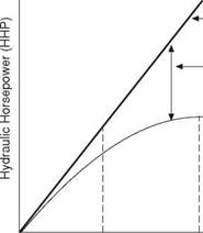
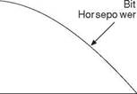
Figure 2 Horsepower Used in Drillstring and Across Nozzles of Bit
As stated above, it is desirable to optimise the pressure losses through the nozzles (and therefore the cleaning of the bit face) and minimise the sacrificial losses in the drillstring and annulus. There is, for all combinations of drillstring, nozzle size and hole size, an optimum flow rate for which the hydraulic power at the bit is maximised (Figure 2). The analysis and optimization of these pressure losses is generally referred to as, optimising the hydraulic power of the system. The design of an efficient hydraulics programme is an important element of well planning.
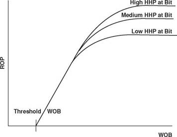
Optimization of the hydraulics of the system is a very important aspect of drilling operations. However, as stated above, the primary function of the drilling fluid is to carry the drilled cuttings to the surface. In order to do this the velocity of the fluid in the annulus will have to be high enough to ensure that the drilled cuttings are efficiently removed. If these cuttings are not removed the drillstring will become stuck and theoretical optimization will be fruitless. Considerations with respect to optimization should therefore only be addressed once the minimum annular velocity for which the cuttings will be removed is achieved. Only then, should any further increase in fluid flowrate be used to improve the pressure loss across the nozzles of the bit and therefore the hydraulic power at the bit face. If the drilled cuttings are not removed from the bit face, the bit wastes valuable effort in regrinding them instead of making new hole. This results in a significant reduction in penetration rate (Figure 3). Once the cuttings are removed from the face of the bit they must then be transported, via the drillpipe/wellbore annulus, to surface. To ensure that the cuttings are removed from the annulus the annular velocity must never be allowed to fall below a certain minimum value. This minimum annular velocity is dependent on the properties of the mud and cuttings for any particular well, and is usually between 100 — 200 ft/min
|
|
|
Figure 3 Impact of Horsepower at the Bit on Rate of Penetration for Given Weight on Bit |
The techniques used to optimise the hydraulics of the system will be described at the end of this chapter. However, optimising the use of the hydraulic horsepower generated by the mud pumps requires the ability to quantify the pressure losses in the drillstring, across the nozzles and in the annulus between the drillstring and wellbore. The principal factors which influence the magnitude of the pressure losses in the system are:
• The geometry of circulating system (e. g. I. D. of drillpipe, length of drillpipe)
• The flowrate through the system
• The flow regime in which the fluid is flowing (laminar/turbulent)
• The rheological properties of the circulating fluid
The geometry of the system and the flowrate through the system are generally fixed
by a wide range of considerations. The geometry of the system is determined by well design and drilling operational considerations. Whilst the minimum flowrate through the system is dictated primarily by the annular velocity required to clean the drilled cuttings from the annulus. The maximum flowrate will be limited by the maximum power output by the mudpumps and the maximum pressures which can be tolerated by the pumping system.
It is therefore only necessary to understand the nature of the flow regime and rheological properties of the fluid and their influence on the pressure losses in the system.
2. FLOW REGIME AND REYNOLDS NUMBER
2.1 Introduction
The first published work on fluid flow patterns in pipes and tubes was done by Osborne Reynolds. He observed the flow patterns of fluids in cylindrical tubes by injecting dye into the moving stream. On the basis of this type of work it is possible to identify two distinct types of flow pattern (Figure 4) :
Laminar Flow (Streamline or Viscous flow) :
In this type of flow, layers of fluid move in streamlines or laminae. There is no microscopic or macroscopic intermixing of the layers. Laminar flow systems are generally represented graphically by streamlines.
Turbulent Flow :
In turbulent flow there is an irregular random movement of fluid in a transverse direction to the main flow. This irregular, fluctuating motion can be regarded as superimposed on the mean motion of the fluid.
^ Pipe Wall
УУ-////////////////////Х
~ у Laminae A
|
|
|
V//////////////////////A b) Turbulent Flow |
|
Figure 4 Flow Patterns in Pipes |
V/////////////////////A a) Laminar Flow
2.2 Determination of the Laminar/Turbulent Boundary in a Newtonian Fluid:
Reynolds showed that when circulating Newtonian fluids through pipes the onset of turbulence was dependant on the following variables:
• Pipe diameter, d,
• Density of fluid, r
• Viscosity of fluid, ц
• Average flow velocity, v.
He also found that the onset of turbulence occurred when the following combination of these variables exceeded a value of 2100
This is a very significant finding since it means that the onset of turbulence can be predicted for pipes of any size, and fluids of any density or viscosity, flowing at any rate through the pipe. This grouping of variables is generally termed a dimensionless group and is known as the Reynolds number. In field units, this equation is:
N = 928pvd
Re M
Equation 2 Reynolds Number Equation
where,
p = fluid density, lbm/gal v = mean fluid velocity, ft/s d = pipe diameter, in. ц = fluid viscosity, cp.
Reynolds found that as he increased the fluid velocity in the tube, the flow pattern changed from laminar to turbulent at a Reynolds number value of about 2100. However, later investigators have shown that under certain conditions, e. g. with non-newtonian fluids and very smooth conduits, laminar flow can exist at very much higher Reynolds numbers. For Reynolds numbers of between 2,000 and 4,000 the flow is actually in a transition region between laminar flow and fully developed turbulent flow.
EXERCISE 1 Determination of Fluid Flow Regime:
a. Determine whether a fluid with a viscosity of 20 cp and a density of 10 ppg flowing in a 5" 19.5 lb/ft (I. D. = 4.276") drillpipe at 400 gpm is in laminar or turbulent flow.
b. What is the maximum flowrate to ensure that the fluid is in laminar flow?
