 Positive Displacement Motors (PDM’s) and Turbodrills
A. POSITIVE DISPLACEMENT MOTORS (PDM)
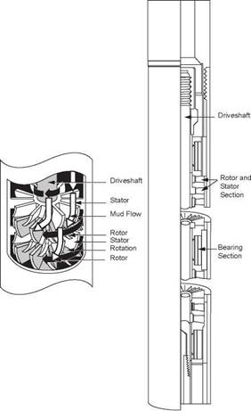
A PDM is a downhole mud motor that uses the reverse Moineau pump principle to drive the bit without rotating the entire drillstring. It can be powered using drilling fluid, air or gas. The tool consists of 4 main sections (Figure 14).
(a) dump valve — a by-pass valve which allows the drillstring to fill up or drain when tripping in or out of the hole
(b) motor assembly — consists of a rubber lined stator which contains a spirally shaped cavity of elliptical cross-section. Running through the length of this cavity is a solid steel shaft which is also spiral in shape. The top end of the shaft or rotor is free, and the lower end fixed to a connecting rod
(c) connecting rod — equipped with a universal joint at each end to
accommodate the eccentric rotation of the rotor and transfer this rotation to the drive shaft
(d) bearing and drive shaft assembly — consists of thrust bearings and a radial
bearing to allow smooth rotation of the drive shaft. The bearings are
lubricated by the mud. The drive shaft is then connected to a bit sub, which is the only external rotating part of the mud motor.
In some PDMs multi-stage (usually 3 stage) motors are now used. When drilling fluid is pumped through the motor it is forced under pressure into cavities between rotor and stator. The design of the motor is such that the rotor is forced to turn clockwise. This rotation is transferred via the drive shaft to the bit.
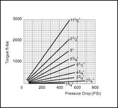
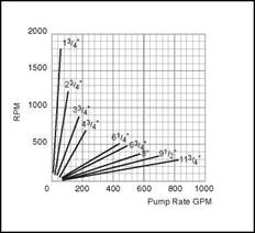
In a PDM drilling torque is proportional to the pressure differential across the motor. When WOB is applied the circulating pressure must increase. As the bit drills off the pressure decreases. It is therefore possible to use the mud pressure gauge as a weight and torque indicator. Experience has shown that the proper weight on bit is achieved when the pump pressure is 100 — 150 psi above free circulating pressure (i. e. when bit hanging free off bottom). Typical specifications and performance curves for a PDM are given in Figure 15.
To deviate a well a bent PDM housing is used or a bent sub is run above the PDM. A bent housing requires the connecting rod assembly to be modified so that the tool has a slight bend. A bent sub can be used to create the same effect.
|
|
|
9/10 |
|
|
Power Unit (Rotor and Stator)
|
|
|
8/9 |
|
О S>] 7/8 |
|
|
|
|
Transmission
|
|
Unit
■ Bearing
|
|
|
4/5 |
|
|
|
3/4 |
Tubular Housings and Stabilizer
|
|
|
Figure 14 PDM assembly |
|
) 1/2 |
|
|
One effect which must be taken into account when drilling with a downhole motor is reactive torque. This is the tendency for the drillstring to turn in the opposite direction from the bit. As the rotor turns to the right, the stator is subjected to a left — turning force. Depending on the type of formation and length of string the drillpipe will twist, causing the bit to drill to the left. This left hand torque will increase as more WOB and pump pressure are applied. The directional driller must allow for this effect when he orients the bent sub. This is largely a matter of field experience in a particular area.
|
|
|
Figure 15 Typical Performance Specification for a PDM B. TURBODRILLS |
|
|
This is another type of mud motor which turns the bit without rotating the drillstring. Unlike a PDM a turbodrill can only be powered by a liquid drilling fluid. The turbodrill motor consists of bladed rotors and stators mounted at right angles to fluid flow. The rotors are attached to the drive shaft, while the stators are attached to the outer case. Each rotor-stator pair is called a stage; a typical turbodrill may have 75-250 stages. The stators direct the flow of drilling fluid onto the rotor blades, forcing the drice shaft to rotate clockwise (Figure 16). Turbodrills can be used for directional drilling in much the same way as PDMs. Turbodrills are also used in straight-hole
drilling as an alternative to rotary drilling. Such a technique has the following advantages:
(a) String and casing wear reduced
(b) Lower torque applied to string
(c) Higher RPM at bit (better penetration rates).
|
Figure 16 Turbodrill |
Turbodrills are sometimes used with PDC (polycrystalline diamond compact) bits in North Sea wells to reduce costs in long bit runs. A typical turbodrill assembly for North Sea use is given in Figure 17.
Stabilizer
|
50 ft |
2 Monel Drill Collars
Stabilizer Circulating Sub
25 ft
71/8 in.240 Turbodrill
7 ft
1 1/2 ft
|
1 1/2 ft. |
|
D_ |
Near Bit Stabilizer Bit
Figure 17 Turbodrill assembly


