 PRIMARY CEMENTING
The objective of a primary cement job is to place the cement slurry in the annulus behind the casing. In most cases this can be done in a single operation, by pumping cement down the casing, through the casing shoe and up into the annulus. However, in longer casing strings and in particular where the formations are weak and may not be able to support the hydrostatic pressure generated by a very long colom of cement slurry, the cement job may be carried out in two stages. The first stage is completed in the manner described above, with the exception that the cement slurry does not fill the entire annulus, but reaches only a pre-determined height above the shoe. The second stage is carried out by including a special tool in the casing string which can be opened, allowing cement to be pumped from the casing and into the annulus. This tool is called a multi stage cementing tool and is placed in the casing string at the point at which the bottom of the second stage is required. When the second stage slurry is ready to be pumped the multi stage tool is opened and the second stage slurry is pumped down the casing, through the stage cementing tool and into the annulus, as in the first stage. When the required amount of slurry has been pumped, the multi stage tool is closed. This is known as a two stage cementing operation and will be discussed in more detail later.
The height of the cement sheath, above the casing shoe, in the annulus depends on the particular objectives of the cementing operations. In the case of conductor and surface casing the whole annulus is generally cemented so that the casing is prevented from buckling under the very high axial loads produced by the weight of the wellhead and BOP. In the case of the intermediate and production casing the top of the cement sheath (Top of Cement — TOC) is generally selected to be approximately 300-500 ft. above any formation that could cause problems in the annulus of the casing string being cemented. For instance, formations that contain gas which could migrate to surface in the annulus would be covered by the cement. Liners are generally cemented over their entire length, all the way from the liner shoe to the liner hanger.
1.2 Downhole cementing equipment
In order to carry out a conventional primary cement job some special equipment must be included in the casing string as it is run.
|
|
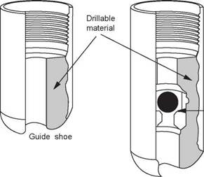
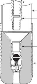
• Guide shoe — A guide (Figure 5) shoe is run on the bottom of the first joint of casing. It has a rounded nose to guide the casing past any ledges or other irregularities in the hole.
|
|
|
Float shoe |
|
Float valve |
|
Figure 5 Guide shoe and float shoe |
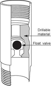
• Float collar — A float collar (Figure 6) is positioned 1 or 2 joints above the guide shoe. It acts as a seat for the cement plugs used in the pumping and displacement of the cement slurry. This means that at the end of the cement job there will be some cement left in the casing between the float collar and the guide shoe which must be drilled out.
The float collar also contains a non-return valve so that the cement slurry cannot flow back up the casing. This is necessary because the cement slurry in the annulus generally has a higher density than the displacing fluid in the casing, therefore a U-tube effect is created when the cement is in position and the pumps are stopped. Sometimes the guide shoe also has a non-return valve as an extra precaution. It is essential that the non-return valves are effective in holding back the cement slurry.
%
|
Figure 6 Float collar |
The use of a non-return valve means that as the casing is being run into the borehole the fluid in the hole cannot enter the casing from below. This creates a buoyancy effect which can be reduced by filling up the casing from the surface at regular intervals while the casing is being run (every 5 — 20 joints). This filling up process increases the running in time and can be avoided by the use of automatic or differential fill up devices fitted to the float collar or shoe. These devices allow a controlled amount of fluid to enter the casing at the bottom of the string. The ports through which the fluid enters are blocked off before the cement job begins. The use of a differential fill-up device also reduces the effect of surge pressures on the formation.
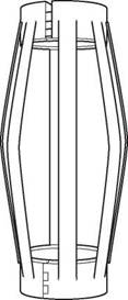
Centralisers are particularly required in deviated wells where the casing tends to lie on the low side of the hole. On the high side there will be little resistance to flow, and so cement placement will tend to flow up the high side annular space. Mud channels will tend to form on the low side of the hole, preventing a good cement job. Each centraliser is hinged so that it can be easily clamped onto the outside of the casing and secured by a retaining pin. The centraliser is prevented from moving up and down the casing by positioning the centraliser across a casing coupling or a collar known as a stop collar. The spacing of centralisers will vary depending on the requirements of each cement job. In critical zones, and in highly deviated parts of the well, they are closely spaced, while on other parts of the casing string they may not be necessary at all. A typical programme might be:
1 centraliser immediately above the shoe 1 every joint on the bottom 3 joints 1 every joint through the production zone 1 every 3 joints elsewhere
|
Figure 7 Casing Centraliser |
|
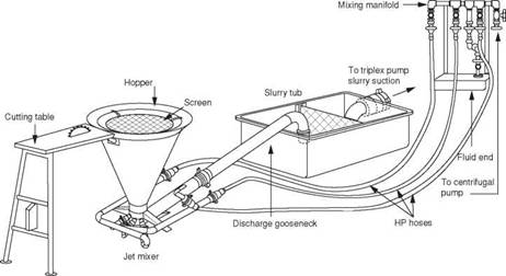
Figure 8 Cement unit showing jet mixer |
|
% |
1.3 Surface cementing equipment Mixing and pumping facilities:
On most rigs cement powder and additives are handled in bulk, which makes blending and mixing much easier. For large volume cement jobs several bulk storage bins may be required on the rig. On offshore rigs the cement is transferred pneumatically from supply boats to the storage bins.
For any cement job there must be sufficient water available to mix the slurry at the desired water/cement ratio when required. The mix water must also be free of all contaminants.
The water is added to the cement in a jet mixer (Figure 8). The mixer consists of a funnel shaped hopper, a mixing bowl, a water supply line and an outlet for the slurry. As the mixwater is pumped across the lower end of the hopper a venturi effect is created and cement powder is drawn down into the flow of mixwater and a slurry is created. The slurry flows into a slurry tub where its density is measured. The density of the slurry should be regularly checked during the cement job since this is the primary means by which the quality of the slurry is determined. If the density of the slurry is correct then the correct amount of mixwater has been mixed with the cement powder. Samples can be taken directly from the mixer and weighed in a standard mud balance or automatic devices (densometers) can also be used.
Various types of cement pumping units are available. For land based jobs they can be mounted on a truck, while skid mounted units are used offshore. The unit normally has twin pumps (triplex, positive displacement) which may be diesel powered or driven by electric motors. These units can operate at high pressures (up to 20,000 psi) but are generally limited to low pumping rates. Most units are capable of mixing and displacing 50 — 70 cubic feet of slurry per minute. In order to minimise contamination by the mud in the annulus a preflush or spacer fluid is pumped ahead of the cement slurry. The actual composition of the spacer depends
on the type of mud being used. For water based muds the spacer fluid is often just water, but specially designed fluids are available. The volume of spacer is based on the need to provide sufficient separation of mud and cement in the annulus (20 — 50 bbls of spacer is common).
|
Figure 9 Cement Head |
Cementing heads:
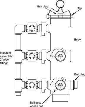
The cement head provides the connection between the discharge line from the cement unit and the top of the casing (Figure 9). This piece of equipment is designed to hold the cement plugs used in the conventional primary cement job. The cement head makes it possible to release the bottom plug, mix and pump down the cement slurry, release the top plug and displace the cement without making or breaking the connection to the top of the casing. For ease of operation the cement head should be installed as close to rig floor level as possible. The cement jobs will be unsuccessful if the cement plugs are installed in the correct sequence or are not released from the cementing head.
Mud is normally used to displace the cement slurry. The cement pumps or the rig pumps may be used for the displacement. It is recommended that the cement slurry is displaced at as high a rate as possible. High rate displacement will aid efficient mud displacement. It is highly unlikely that it will be possible to achieve turbulence in the cement slurry since it is so viscous and has such a high density. However, it may be possible to generate turbulence in the spacer and this will result in a more efficient displacement of the mud.
%
1.4 Single Stage Cementing Operation
The single stage primary cementing operation is the most common type of cementing operation that is conducted when drilling a well. The procedure for performing a single stage cementing operation (Figure 10) will be discussed first and then the procedure for conducting a multiple stage and stinger cementing operations will be discussed.
|
Circulating mud
• Plug release pin in О Plug release pin out |
|
Displacing |
|
Displacing |
|
End of job |
|
Displacing — Fluid |
|
Pumping spacer and slurry |
|
^ ^-Spacer |
|
_ Original mud |
|
Jt |
|
_Slurry |
Figure 10 Single Stage Cementing Operation
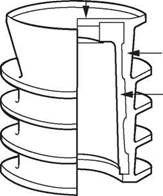
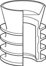
In the case of the single stage operation, the casing with all of the required cementing accessories such as the float collar, centralisers etc. is run in the hole until the shoe is just a few feet off the bottom of the hole and the casing head is connected to the top of the casing. It is essential that the cement plugs are correctly placed in the cement head. The casing is then circulated clean before the cementing operation begins (at least one casing volume should be circulated). The first cement plug (wiper plug) shown in Figure 11, is pumped down ahead of the cement to wipe the inside of the casing clean. The spacer is then pumped into the casing. The spacer is followed by the cement slurry and this is followed by the second plug (shut-off plug) shown in Figure 12. When the wiper plug reaches the float collar its rubber diaphragm is ruptured, allowing the cement slurry to flow through the plug, around the shoe, and up into the annulus. At this stage the spacer is providing a barrier to mixing of the cement and mud. When the solid, shut-off plug reaches the float collar it lands on the wiper plug and stops the displacement process. The pumping rate should be slowed down as the shut-off plug approaches the float collar and the shut-off plug should be gently bumped into the bottom, wiper plug. The casing is often pressure tested at this point in the operation. The pressure is then bled off slowly to ensure that the float valves, in the float collar and/or casing shoe, are holding.
|
|
The displacement of the top plug is closely monitored. The volume of displacing fluid necessary to bump the plug should be calculated before the job begins. When the pre-determined volume has almost been completely pumped, the pumps should be slowed down to avoid excessive pressure when the plug is bumped. If the top plug does not bump at the calculated volume (allowing for compression of the mud) this may be because the top, shut-off plug has not been released. If this is the case, no more fluid should be pumped, since this would displace the cement around the casing shoe and up the annulus. Throughout the cement job the mud returns from the annulus should be monitored to ensure that the formation has not been broken down. If formation breakdown does occur then mud returns would slow down or stop during the displacement operation.
The single stage procedure can be summarised as follows:
1. Circulate the casing and annulus clean with mud (one casing volume pumped)
2. Release wiper plug
3. Pump spacer
4. Pump cement
5. Release shut-off plug
6. Displace with displacing fluid (generally mud) until the shut-off plug lands on the float collar
7. Pressure test the casing
|
|
|
Rupture Disk |
|
Moulded Elastomer |
|
Aluminium Core |
|
Figure 11 Bottom Plug (wiper plug) |
|
Figure 12 Top Plug (shut off plug) |
1.5 Multi — Stage Cementing Operation
When a long intermediate string of casing is to be cemented it is sometimes necessary to split the cement sheath in the annulus into two, with one sheath extending from the casing shoe to some point above potentially troublesome formations at the bottom of the hole, and the second sheath covering shallower troublesome formations. The placement of these cement sheaths is known as a multi-stage cementing operation (Figure 13). The reasons for using a multi-stage operation are to reduce:
|
t |
|
) |
|
V [ fa |
|
P Ґ |
|
|
|
if |
Figure 13 Multi-Stage Cementing Operation
The procedure for conducting a multi-stage operation is as follows:
First stage
The procedure for the first stage of the operation is similar to that described in Section 4.3 above, except that a wiper plug is not used and only a liquid spacer is pumped ahead of the cement slurry. The conventional shut-off plug is replaced by a plug with flexible blades. This type of shut-off plug is used because
it has to pass through the stage cementing collar which will be discussed below. It is worth noting that a smaller volume of cement slurry is used, since only the lower part of the annulus is to be cemented. The height of this cemented part of the annulus will depend on the fracture gradient of the formations which are exposed in the annulus (a height of 3000′ — 4000′ above the shoe is common).
Second stage
The second stage of the operation involves the use of a special tool known as a stage collar (Figure 14), which is made up into the casing string at a pre-determined position. The position often corresponds to the depth of the previous casing shoe. The ports in the stage collar are initially sealed off by the inner sleeve. This sleeve is held in place by retaining pins. After the first stage is complete a special dart is released form surface which lands in the inner sleeve of the stage collar. When a pressure of 1000 — 1500 psi is applied to the casing above the dart, and therefore to the dart, the retaining pins on the inner sleeve are sheared and the sleeve moves
|
X |
down, uncovering the ports in the outer mandrel. Circulation is established through the stage collar before the second stage slurry is pumped.
The normal procedure for the second stage of a two stage operation is as follows:
1 Drop opening dart
2 Pressure up to shear pins
3 Circulate though stage collar whilst the first stage cement is setting
4 Pump spacer
5 Pump second stage slurry
6 Release closing plug
7 Displace plug and cement with mud
8 Pressure up on plug to close ports in stage collar and pressure test the casing.
|
Figure 14 Multi-Stage Cementing Collar |
To prevent cement falling down the annulus a cement basket or packer may be run on the casing below the stage collar. If necessary, more than one stage collar can be run on the casing so that various sections of the annulus can be cemented. One disadvantage of stage cementing is that the casing cannot be moved after the first stage cement has set in the lower part of the annulus. This increases the risk of channelling and a poor cement bond.
For large diameter casing, such as conductors and surface casing, conventional cementing techniques result in:
• The potential for cement contamination during pumping and displacement
• The use of large cement plugs which can get stuck in the casing
• Large displacement volumes
• Long pumping times
• Large volume of cement left inside the casing between float collar and shoe.
An alternative technique, known as a stinger cement job, is to cement the casing through a tubing or drillpipe string, known as a cement stinger, rather than through the casing itself.
In the case of a stinger cement job the casing is run as before, but with a special float shoe (Figure 15) rather than the conventional shoe and float collar. A special sealing adapter, which can seal in the seal bore of the seal float shoe, is attached to the cement stinger. Once the casing has been run, the cementing string (generally tubing or drillpipe), with the seal adapter attached, is run and stabbed into the float shoe. Drilling mud is then circulated around the system to ensure that the stinger and annulus are clear of any debris. The cement slurry is then pumped with liquid spacers ahead and behind the cement slurry. No plugs are used in this type of cementing operation since the diameter of the stinger is generally so small that contamination of the cement is unlikely if a large enough liquid spacer is used. The cement slurry is generally under-displaced so that when the seal adapter on the stinger is pulled from the shoe the excess cement falls down on top of the shoe. This can be subsequently drilled out when the next hole section is being drilled. Under-displacement however ensures that the cement slurry is not displaced up above the casing shoe, leaving spacer and drilling mud across the shoe. After the cement has been displaced, and the float has been checked for backflow, the cement stinger can be retrieved. This method is suitable for casing diameters of 13 3/8" and larger. The main disadvantage of this method is that for long casing strings rig time is lost in running and retrieving the inner string.
|
|
|
Tool joint adapter Casing Sealing adapter |
|
Sealing sleeve |
|
Super seal float shoe |
|
|
|
Drillpipe or tubing |
|
Special float shoe |
|
Cement |
Figure 15 Stinger Cementing Operation
Liners are run on drillpipe and therefore the conventional cementing techniques cannot be used for cementing a liner. Special equipment must be used for cementing these liners.
As with a full string of casing the liner has a float collar and shoe installed. In addition there is a landing collar, positioned about two joints above the float collar (Figure 16). A wiper plug is held on the end of the tailpipe of the running string by shear pins.
|
|
|
Cementing manifold______ |
|
Cementing head |
|
Landing collar |
|
Setting tool Hanger slips Wiper plug Centralizers |
|
Float collar |
|
Float shoe |
|
Figure 16 Liner Cementing Equipment |
The liner is run on drillpipe and the hanger is set at the correct point inside the previous casing string. Mud is circulated to ensure that the liner and the annulus is free from debris, and to condition the mud. Before the cementing operation begins the liner setting tool is backed off to ensure that it can be recovered at the end of the cement job. The cementing procedure is as follows:
1 Pump spacer ahead of cement slurry
2 Pump slurry
3 Release pump down plug
4 Displace cement down the running string and out of the liner into the annulus
5 Continue pumping until the pump down plug lands on the wiper plug.
6 Apply pressure to the pump down plug and shear out the pins on the wiper plug. This releases the wiper plug
7 Both plugs move down the liner until they latch onto landing collar
8 Bump the plugs with 1000 psi pressure
9 Bleed off pressure and check for back flow
Since there is no bottom plug in front of the slurry the wiper plug cleans off debris and mud from the inside of the liner. This material will contaminate the cement immediately ahead of the wiper plug. The spacing between the landing collar and the shoe should be adequate to accommodate this contaminated cement, and thus prevent it from reaching the annulus where it would create a poor cement job around the shoe.
To promote a good cement job, cement in excess of that required to fill the annulus between the liner and the borehole is used. This excess cement will pass up around the liner top and settle on top of the liner running assembly. Once the cement is in place the liner setting tool is quickly picked up out of the liner. With the tail pipe above the liner top the excess cement can be reverse circulated out. The setting tool can then be retrieved.
In practice it is very difficult to obtain a good cement job on a liner. The main reasons for this are:
(a) Minimal annular clearances
A 7" OD liner run in an 8 1/2" hole gives a clearance of only 3/4" (assuming the liner is perfectly centred). This small clearance means that:
• It is difficult to run the liner (surge pressure)
• High pressure drops occur during circulation (lost circulation problems)
• It is difficult to centralise the liner
• Cement placement is poor (channeling)
When the cement comes in contact with mud or mud cake it may develop high viscosity. The increased pump pressure required to move this contaminated cement up the annulus may cause formation breakdown. Fluid loss additives must be used to prevent dehydration of the cement which may cause bridging in the annulus.
Due to risk of sticking the setting tool, most operators want to be free of the liner before cementing begins. By disconnecting the setting tool the liner cannot be moved during the cement job. This lack of movement reduces the efficiency of cement placement. Due to these problems it is often necessary to carry out a remedial squeeze job at the top of the liner (Figure17). It is becoming more common these days to remain latched on top of the liner and rotate the liner whilst the cement is being displaced into position. A special piece of liner running equipment, known as a rotating liner assembly, is used for this purpose.
|
Tubing |
|
|
|
Retainer or retrievable packer |
|
Top of liner |
|
Figure 17 Remedial squeeze job on a liner |
