 Rheological models
A mathematical description of the viscous forces present in a fluid is required for the development of equations which describe the pressure losses in the drillstring and annulus. These forces are represented by the rheological model of the fluid. The rheological models which are generally used by drilling engineers to describe drilling fluids are:
a. Newtonian model
b. Non — Newtonian Models the Bingham plastic model
the power-law model.
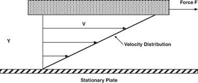
The viscous forces present in a simple Newtonian fluid are characterised by a single coefficient — the ‘coefficient of viscosity’ or as it is normally referred to the viscosity. Examples of Newtonian fluids are water, gases and high gravity oils. To understand the nature of viscosity, consider a fluid contained between two large parallel plates of area, A which are separated by a small distance, Y (Figure 5). The upper plate, which is initially at rest, is set in motion at a constant velocity, v. After sufficient time has passed for steady motion to be achieved a constant force F is required to keep the upper plate moving at constant velocity.
|
Plate moving at velocity (v)
Figure 5 Model of Viscous Forces in Fluids |
The relationship between these parameters can be found experimentally to be given by:
F V
— = F V A L
The term F/A is called the shear stress and is generally represented by the Greek term, t :
T = F A
|
|
The velocity gradient v/L is an expression of the fluid shear rate and is generally represented by the Greek term g :
Y = V = dv L dL
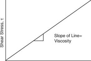
If the results of the experiment described above are plotted on a graph then the relationship would be defined by a straight line as shown in Figure 6.
|
|
Figure 6 Shear Stress vs. Shear Rate Relationship for Newtonian Fluids
The equation of the straight line relationship is known as the rheological model which represents the relationship between the shear rate and shear stress and can be expressed as:


