 CASING TERMINOLOGY
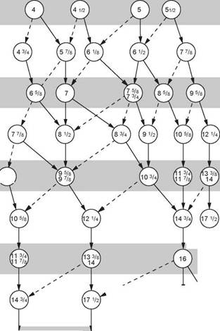
There are a set of generic terms used to describe casing strings. These terms are shown in Figure 2. The classification system is based on the specific function of the casing string so, for instance, the function of the surface string shown in Figure 2 is to support the wellhead and BOp stack. Although there is no direct relationship between the size of casing and its function, there is a great deal of similarity in the casing sizes used by operators in the North sea. The chart in figure 3 shows the most common casing size and hole size configurations. The dotted lines represent less commonly used configurations. The terms which are generally used to classify casing strings are shown below. The casing sizes shown alongside the casing designation are those that are generally used in the North sea.
|
% |
1.1 Conductor Casing (30” O. D.)
The conductor is the first casing string to be run, and consequently has the largest diameter. It is generally set at approximately 100ft below the ground level or seabed. Its function is to seal off unconsolidated formations at shallow depths which, with continuous mud circulation, would be washed away. The surface formations may also have low fracture strengths which could easily be exceeded by the hydrostatic pressure exerted by the drilling fluid when drilling a deeper section of the hole. In areas where the surface formations are stronger and less likely to be eroded the conductor pipe may not be necessary. Where conditions are favourable the conductor may be driven into the formation and in this case the conductor is referred to as a stove pipe.
1.2 Surface Casing (20” O. D.)
The surface casing is run after the conductor and is generally set at approximately 1000 — 1500 ft below the ground level or the seabed. The main functions of surface casing are to seal off any fresh water sands, and support the wellhead and BOp equipment. The setting depth of this casing string is important in an area where abnormally high pressures are expected. If the casing is set too high, the formations below the casing may not have sufficient strength to allow the well to be shut-in and killed if a gas influx occurs when drilling the next hole section. This can result in the formations around the casing cratering and the influx flowing to surface around the outside of the casing.
1.3 Intermediate Casing (13 3/8” O. D.)
Intermediate (or protection) casing strings are used to isolate troublesome formations between the surface casing setting depth and the production casing setting depth. The types of problems encountered in this interval include: unstable shales, lost circulation zones, abnormally pressured zones and squeezing salts. The number of intermediate casing strings will depend on the number of such problems encountered.
1.4 Production Casing (9 5/8” O. D.)
The production casing is either run through the pay zone, or set just above the pay zone (for an open hole completion or prior to running a liner). The main purpose of this casing is to isolate the production interval from other formations (e. g. water bearing sands) and/or act as a conduit for the production tubing. since it forms the conduit for the well completion, it should be thoroughly pressure tested before running the completion.
A liner is a short (usually less than 5000ft) casing string which is suspended from the inside of the previous casing string by a device known as a liner hanger. The liner hanger is attached to the top joint of the casing in the string. The liner hanger consists of a collar which has hydraulically or mechanically set slips (teeth) which, when activated, grip the inside of the previous string of casing. These slips support the weight of the liner and therefore the liner does not have to extend back up to the wellhead. The overlap with the previous casing (liner lap) is usually 200ft — 400ft. Liners may be used as an intermediate string or as a production string.
|
Casing and liner size (inches) |
|
Casing and liner size (inches) |
|
Casing and liner size (inches) |
|
|
|
Bit and hole size (inches) |
|
Bit and hole size (inches) |
|
Casing and liner size (inches) 18 5/8 |
|
Bit and hole size (inches) |
|
Bit and hole size (inches) |
|
Casing and liner size (inches) v6y |
|
© (20) ^26 © © |
Figure 3 Casing string sizes The advantages of running a liner, as opposed to a full string of casing, are that:
• A shorter length of casing string is required, and this results in a significant cost reduction;
• The liner is run on drillpipe, and therefore less rig time is required to run the string;
• The liner can be rotated during cementing operations. This will significantly improve the mud displacement process and the quality of the cement job.
After the liner has been run and cemented it may be necessary to run a casing string of the same diameter as the liner and connect onto the top of the liner hanger, effectively extending the liner back to surface. The casing string which is latched onto the top of the liner hanger is called a tie-back string. This tie-back string may be required to protect the previous casing string from the pressures that will be encountered when the well is in production.
|
% |
In addition to being used as part of a production string, liners may also be used as an intermediate string to case off problem zones before reaching the production zone. In this case the liner would be known as a drilling liner (Figure 2). Liners may also be used as a patch over existing casing for repairing damaged casing or for extra protection against corrosion. In this case the liner is known as a stub liner.
