 EXERCISE 1 Calculating the Position of a Survey Station
Whilst drilling a deviated well, the Measured Depth, Inclination and Azimuth of the well are measured at station 23 (See survey data below). Calculate the:
North and East co-ordinates,
TVD
vertical section and dogleg severity
of the next station according to the average angle method
The target bearing is 095o.
|
STATION |
MD |
INC. |
AZI. |
N |
E |
TVD |
VS |
|
22 |
3135 |
24.5 |
92 |
-30.78 |
344.60 |
3086.95 |
345.02 |
|
23 |
3500 |
25.5 |
92.5 |
Exercise 1 Calculating the Position of a Survey Station
|
S |
|
N |
A
|
|
(i) Average Angles:
a = 24.5 + 25.5 2
|
(Average Drift Angle) |
a = 25 0
в = 92 + 92.5 2
в = 92.250 (Average Azimuth Angle)
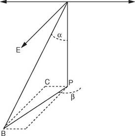
(ii) Course displacement (Station 22 to 23): AB = MDB — MDA = course length Course displacement (PB) = AB sin a PB = 365 Sin 250 = 154 ft
(iii) True Vertical Depth Station 23:
TVD Station 23 = TVD Station 22 + True vertical distance (PA)
True vertical distance (PA) = AB cos a
PA = 365 Cos 250
= 330.80 ft
TVD Station 23 = 3086.95 + 330.80
|
= 3417.75 ft N
|
(iv) Northerly Position Station 23
(Note that the well trajectory is in a southerly direction and that the calculations must take account of this):
From the plan view above:
NB = Na + AN
Northerly Position Station 23 = Station 22 (N) — PC PC = Northing Displacement = PB Sin 2.25 PC= 154 Sin 2.25 = 6.05 ft
Northerly Position Station 23 = -30.78 — 6.05 = -36.83 ft
(v)Easterly Position Station 23 From the plan view above:
EB = Ea + ^E
Easterly Position Station 23 = Station 22 (E) + CB CB = Easting Displacement = PB Cos (в — 90)
= 153.9 ft
Easterly Position Station 23 = 344.60 + 153.9 = 495.8 ft
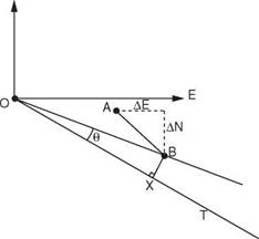
(v) Vertical Section:
From the plan view of the above:
Vertical section (VS) = OX = OB cos 0
closure OB = лjE2B + N2B
Closure = V36.832 + 495.82
= 497.19 ft
Angle 0 = Angle TOE — Angle BOE (target bearing — bearing of B)
tan (Angle BOE) = Northing B
Easting B
= 36.83 495.8
|
tan BOE |
= 0.0743
Angle BOE = 4.250
0 = Angle TOE — Angle BOE (target bearing — bearing of B) = 95 — 94.25 = 0.750
Vertical section(VS) = OX = OB cos 0 = 497.19 Cos 0.75 = 497.15
(vii) Dog leg severity (DLS):
Dog leg severity (DLS) = cos-1( cosaA cosaB + sinaA sinaB cos (PA — PB)) = cos-1( cos24.5 cos25.5 + sin24.5 sin25.5 cos (92 — 92.5))
= cos-1(0.9998)
DLS = 1.15
Since this DLS is measured over 365 ft it can be expressed as:
= 115 x 100 = 0.310 per 100ft 365
|
STATION |
MD |
INC. |
AZI. |
N |
E |
TVD |
VS |
|
22 |
3135 |
24.5 |
92 |
-30.78 |
344.60 |
3086.95 |
345.O2 |
|
23 |
3500 |
25.5 |
92.5 |
-36.83 |
495.8 |
3417.75 |
497.15 |
1. INTRODUCTION
2. MWD SYSTEMS
2.1 Power Sources
3. MWD — DIRECTIONAL TOOLS
3.1 Calculations for Inclination, Toolface and Azi muth
3.2 Normal Surveying Routine
3.3. Accuracy of MWD Surveys
4. MWD — GAMMA RAY TOOLS
5. TRANSMISSION AND CONTROL SYSTEMS
6. SURFACE SYSTEM
7. example SYSTEMS
|
<? о |
|
a |
|
% |
|
%E^4 |
|
Or |
Having worked through this chapter the student will be able to: General:
• Describe the benefits of using and the general principles behind the MWD concept.
• describe the applications of MWD tools.
• Describe the component parts of an MWD system.
• Describe the three mud pulse telemetry techniques.
• Describe the advantages and disadvantages of the various types of Power systems.
• Describe the directional surveying equipment used in MWD tools.
• Describe the Petrophysical and drilling sensors used in MWD tools.
Calculation of Inclination, toolface and azimuth:
• Calculate the inclination, toolface and azimuth using data from accelerometers and magnetometers.
• Describe the operations involved in conducting a survey using an MWD system. Transmission and Control Systems:
• Describe the transmisssion and control systems used in MWD tools.
• Describe the surface systems used in MWD systems.

