 Measurement While Drilling Tool
1. INTRODUCTION
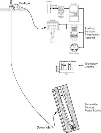
Measurement While Drilling — MWD systems allow the driller to gather and transmit, information from the bottom of the hole back to the surface without interrupting normal drilling operations. This information can include directional deviation data, data related to the petrophysical properties of the formations and drilling data, such as WOB and torque. The information is gathered and transmitted to surface by the relevant sensors and transmission equipment which is housed in a non-magnetic drill collar in the bottom hole assembly (Figure 1). This tool is known as a Measurement While Drilling Tool — MWD Tool. The data is transmitted through the mud column in the drillstring, to surface. At surface the signal is decoded and presented to the driller in an appropriate format. The transmission system is known as mud pulse telemetry and does not involve any wireline operations.
Commercial MWD systems were first introduced in the North Sea in 1978 as a more cost effective method of taking directional surveys. To take a directional survey using conventional wireline methods may take 1-2 hours. Using an MWD system a survey takes less than 4 minutes. Although MWD operations are more expensive than wireline surveying an operating company can save valuable rig time, which is usually more significant in terms of cost.
More recently MWD companies have developed more complicated tools which will provide not only directional information and drilling parameters (e. g. torque, WOB) but also geological data (e. g. gamma ray, resistivity logs). The latter tools are generally referred to as Logging While Drilling — LWD Tools. As more sensors are added the transmission system must be improved and so MWD tools are becoming more sophisticated. Great improvements have been made over the past few years and MWD tools are now becoming a standard tool for drilling operations.
All MWD systems have certain basic similarities (Figure 1)
— a downhole system which consists of a power source, sensors, transmitter and control system.
— a telemetry channel (mud column) through which pulses are sent to surface.
— a surface system which detects pulses, decodes the signal and presents results (numerical display, geological log, etc.).
The main difference between the 3 MWD systems currently available is the method by which the information is transmitted to surface. All three systems encode the data to be transmitted into a binary code and transmitting this data as a series of pressure pulses up the inside of the drillstring. The process of coding and decoding the data will be described below. The only difference between the systems is the way in which the pressure pulses are generated (Figure 2).
(i) Negative Mud Pulse Telemetry
In all systems fluid must be circulating through the drillstring. In the negative mud pulse system a valve inside the MWD tool opens and allows a small volume of mud to escape from the drill string into the annulus. The opening and closing of this valve creates a small drop in standpipe pressure (50 — 100 psi), which can be detected by a transducer on surface.
In the positive mud pulse system a valve inside the MWD tool partially closes, creating a temporary increase in standpipe pressure.
(iii) Frequency Modulation (Mud siren)
In the frequency modulation system a standing wave is set up in the mud column by a rotating slotted disc. The phase of this continuous wave can be reversed. The data is transmitted as a series of phase shifts.
Many tools also include the ability to record downhole data for later retrieval at surface. Although this undermines the principle of access to ‘real time’ data it allows the operator to gather large volumes of data (typical petrophysical data) and therefore eliminate expensive electric wireline logging operations.
|
|
|
Tool Sizes |
1 3/4" OD — 9 1/2" OD |
|
Max. Temp. |
I50°C |
|
Max. Press. |
20.000psi |
|
Power Sources |
Lithium Balterics(up to KOO hrs op. time) /Turbine |
|
Press. Drop |
13-300 psi @ 1000 epm |
|
Telemetry Type |
Positive Pulse/Negative Pulse/ Siren/EM/Downhole Recording |
|
Sensors |
Directional (MTF/GTF) Petrophysical (Gamma Ray/Resistivity/Neutron) Drilling (Vibralion/DWOB/Torque/Temp./Ann. Press.) |
|
Table 1 MWD Tool Specifications |
Since there is no wireline connection to surface all the power required to operate the MWD tool must be generated downhole. This means that either a battery pack or a turbine-alternator must be installed as part of the MWD tool. The turbine has been the standard method of power generation in the positive pulse and frequency modulation tools. Since less power is required in the negative pulse system batteries have been used. However, with more sensors being added and higher data rates required, batteries are being replaced with turbines in negative pulse systems also.
Turbines have several advantages over batteries (Table 2) but turbines are more prone to mechanical failure. Filter screens are used to prevent debris in the mud from damaging the turbine
|
Power Source |
Advantages |
Disadvantages |
|
Batteries (Li) |
Compact |
Temp. Limit (1500 C) Time Limit (100 to 8(X) hrs) |
|
Turbine |
Higher Power Outpul than Batteries Unlimited Operating Time |
Filters Required |
|
Table 2 Advantages and Disadvantages of MWD Power Systems |
