 RIG-SITE OPERATIONS
Casing leaks are often caused by damaging the threads while handling and running the casing on the rig. It has also been known for a joint of the wrong weight or grade of casing to be run in the wrong place, thus creating a weak spot in the string. such mistakes are usually very expensive to repair, both in terms of rig time and
materials. It is important, therefore, to use the correct procedures when running the casing.
(a) When the casing arrives at the rig site the casing should be carefully stacked in the correct running order. This is especially important when the string contains sections of different casing grades and weights. On offshore rigs, where deck space is limited, do not stack the casing too high or else excessive lateral loads will be imposed on the lowermost row. Casing is off-loaded from the supply boat in reverse order, so that it is stacked in the correct running order
(b) The length, grade, weight and connection of each joint should be checked and each joint should be clearly numbered with paint. The length of each joint of casing is recorded on a tally sheet. If any joint is found to have damaged threads it can be crossed off the tally sheet. The tally sheet is used by the Drilling engineer to select those joints that must be run so that the casing shoe ends up at the correct depth when the casing hanger is landed in the wellhead.
(c) While the casing is on the racks the threads and couplings should be thoroughly checked and cleaned. Any loose couplings should be tightened
(d) Casing should always be handled with thread protectors in place. These need not be removed until the joint is ready to be stabbed into the string.
1.12 Casing Running Procedures
(a) Before the casing is run, a check trip should be made to ensure that there are no tight spots or ledges which may obstruct the casing and prevent it reaching bottom
(b) The drift I. D. of each joint should be checked before it is run.
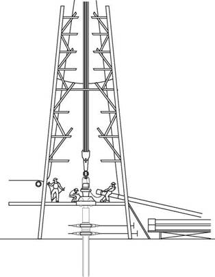
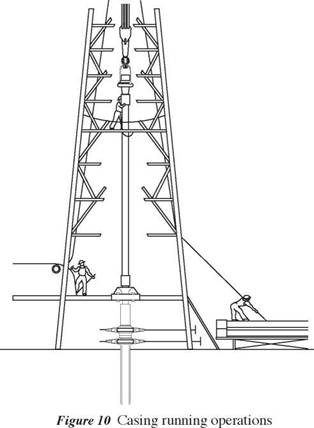
(c) Joints are picked up from the catwalk and temporarily rested on the ramp. A single joint elevator is used to lift the joint up through the “V” door into the derrick (figure 10).
(d) A service company (casing crew) is usually hired to provide a stabber and one or two floormen to operate the power tongs. The stabbing board is positioned at the correct height to allow the stabber to centralise the joint directly above the box of the joint suspended in the rotary table. The pin is then carefully stabbed into the box and the power tongs are used to make up the connection slowly to ensure that the threads of the casing are not cross threaded. Care should be taken to use the correct thread compound to give a good seal. The correct torque is also important and can be monitored from a torque gauge on the power tongs. On buttress casing there is a triangle stamped on the pin end as a reference mark. The coupling should be made up to the base of the triangle to indicate the correct make-up.
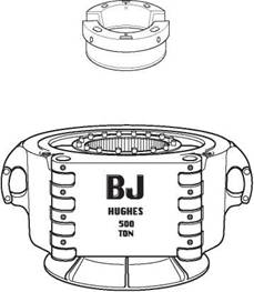
(e) As more joints are added to the string the increased weight may require the use of heavy duty slips (spider) and elevators (figure 11).
|
CD |
|
|
|
|
(f) If the casing is run too quickly into the hole, surge pressures may be generated below the casing in the open hole, increasing the risk of formation fracture. A running speed of 1000 ft per hour is often used in open hole sections. If the casing is run with a float shoe the casing should be filled up regularly as it is run, or the casing will become buoyant and may even collapse, under the pressure from the mud in the hole.
(g) The casing shoe is usually set 10-30 ft off bottom.
|
Figure 11 Heavy duty casing elevators 7.3 Casing Landing Procedures |
After the casing is run to the required depth it is cemented in place while suspended in the wellhead. The method used for landing the casing will vary from area to area, depending on the forces exerted on the casing string after the well is completed. These forces may be due to changes in formation pressure, temperature, fluid density and earth movements (compaction). These will cause the casing to either shrink or expand, and the landing procedure must take account of this. There are basically 3 different ways in which the casing can be cemented and landed:
• landing the casing and cementing;
• suspending the casing, conducting the cement job and then applying additional tension when the cement has hardened;
• landing the casing under compression;
The first case does not require any action after the cementing operation is complete. The casing is simply landed on a boll-weevil hanger and cemented in place. additional tension (over and above the suspended weight) may however have to be applied to the casing to prevent buckling due to thermal expansion when the well is producing hot fluids. Additional tension can be applied, after the casing has been cemented, by suspending the casing from the elevators during the cementing operation and then applying an overpull (extra tension) to the casing once the cement has hardened.
|
|
The casing would then be landed on a slip and seal assembly. The level of overpull applied to the casing will depend on the amount of buckling load that is anticipated due to production. The third option may be required in the case that the suspended tension reduces the casing’s collapse resistance below an acceptable level. In this case the casing is suspended from the elevators during cementing and then lowered until the desired compression is achieved before setting the slip and seal assembly.
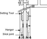
Liners are run on drillpipe with special tools which allow the liner to be run, set and cemented all in one trip (Figure 12). The liner hanger is installed at the top of the liner. The hanger has wedge slips which can be set against the inside of the previous string. The slips can be set mechanically (rotating the drillpipe) or hydraulically (differential pressure). A liner packer may be used at the top of the liner to seal off the annulus after the liner has been cemented. The basic liner running procedure is as follows:
(a) Run the liner on drillpipe to the required depth;
(b) Set the liner hanger;
(c) Circulate drilling fluid to clean out the liner;
(d) Back off (disconnect) the liner hanger setting tool;
(e) Pump down and displace the cement;
(f) Set the liner packer;
|
Cementing Manifold |
(g) Pick up the setting tool, reverse circulate to clean out cement and pull out of hole.
Plug Dropping Head
|
|
|
f t ^ Wiper plug (Shear Type) |
|
Stand-Off Devices |
|
„ | Liner Tie-Back Sleeve |
|
Packoff Bushing -j. (Retrieval-Optional) |
|
|
|
Landing collar |
|
|
|
Float shoe |
|
Float collar |


