 Running and Cementing the 18 5/8"Casing
|
r> __________________________________________________________________________ |
||||
|
———— 1 i U ll |
i |
|||
|
и |
———— L-J———— Л___ |{ —————— »u =fc |
|
n |
||
|
Jf |
||
|
-л——————————— о—————— <||| | П 1 |
||
|
о *————————————————————————————————————— |
|
|
|
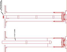
Figure 7 Running the Surface Casing and High Pressure Wellhead Housing — HPWHH |
Having drilled the 26" hole the diverter, riser and hydraulic latch are recovered and laid down. The required length of 18s/g" casing string is made up. An 183/4" high pressure wellhead housing (with a wear bushing installed) is made up onto the top of the casing. The 183/4” Wellhead housing is the high pressure housing onto which the BOP and subsequently Xmas tree will latch and seal. The 13 3/8”, 9 5/8” and 7” casing hangers will all land and seal inside this high pressure housing.
As before a drill pipe cementing stringer, attached to the underside of the running tool, is run down inside the casing. The running tool is then made up (with left hand rotation) into the 183/4" housing (Figure 7). The entire assembly is lowered on drill pipe until the 183/4" housing lands and locks in place in the 30" housing on the
|
Ј |
seabed. The casing annulus is circulated and cemented. The running tool is rotated a few turns to the right for release, and the drill pipe and tool are recovered.
Since the 17V2" hole section will be drilled to considerable depth, a subsea BOP stack and marine riser will generally be required at this stage in the operation. The most common subsea BOP stack configuration used in North Sea operations is the 183/4" 10,000 psi single stack system. The BOP stack is comprised of the following components (Figure 8) :
rm
FLEX JOINT
|
LOWER MARINE RISER PACKAGE |
|
ANNULAR PEVENTER |
HYDRAULIC
CONNECTOR
|
ANNULAR PEVENTER |
|
Ј Ј Ј Ј |
|
SHEAR RAM PIPE RAM PIPE RAM BLINDRAM HYDRAULIC CONNECTOR |
|
«—й |
||||
|
о |
_l н |
■1 |
||
|
о |
_| н |
1 |
||
|
W a la |
||||
|
-E |
о |
_| н |
°L |
|
|
‘3 a 3 |
о |
_| н |
°L of |
|
|
^ )a |
||||
Figure 8 The Subsea BOP
(i) Ahydraulicconnectorwhichlatchesontoandsealsonthe183/4"wellheadhousing.
(ii) A set of four rams and annular preventer.
(iii) A “lower marine riser package” (LMRP) comprising of a hydraulic connector which latches onto the top of the BOP stack (allowing the LMRP to be disconnected from the BOP stack and retrieved on the riser if the rig has to move off location for any reason), a second annular preventer and a flexible joint which allows up to 10o of deflection of the marine riser.
(iv) A marine riser equipped with integral choke and kill lines.
(v) A telescopic joint at surface to accomodate the heave of the rig whilst the marine riser is maintained in constant tension with a heave compensation device.
The BOP stack, LMRP, riser and choke and kill lines are run in one operation. Once the BOP stack is landed and latched onto the 18 3/4" housing the required tension is set on the marine riser tensioners and the flow line is hooked up. The BOP stack is then pressure tested.
1.7 Drilling the 17 1/2" Hole
The 17 1/2" bit and BHA is run and the 171/2" hole section is drilled, taking mud returns to surface. When the casing point has been reached the hole is circulated clean and the drilling assembly recovered in preparation for running the 13 3/8” casing.

