 Solutions to Exercises
Exercise 1 Designing a Deviated Well
The sidetracking of a well requires some preparatory work for the abandonment of the original well but is in essence the same as drilling a deviated well. The solution for this case is given below.
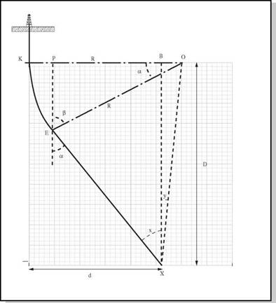
Table Solution 1 presents the results of the design calculations for the sidetrack carried out on a spreadsheet. It also presents the results for the situation which would arise if the buildup angle were increased from 1.5 to 3 degrees per 100ft. It can be seen that increasing the BUR does not significantly affect the along hole depth or the drift angle of the sidetrack. These calculations were carried out on a spread sheet and such sensitivity analysis should be carried out routinely in order to assess the optimum combination of KOP, BUR and drift angle to achieve the objective.
|
a. Drift Angle: |
(NOTE: There are some differences in the results of the hand calculation and the spreadsheet due to rounding errors)
|
|
1.5R _ 360 100 _ 2п
R _ 360 х 100 (Radiusof BU section) 3.0 хп
=3820 ft
TOC o "1-5" h z 3820 — 3500 320
(i) Tan y =
8500 8500
y = 2.16o
3820 — 3500 320
(it) Sin y =—————————————— _———
0X 0X
0X = 8490.3ft
(i) Sin (x + y) =———————
0X
= 3820
= 8490.3
Sinx (x + y) = 0.4499
(x + y) = 26.740
|
x |
= 26.74 — 2.16
= 24.58o (Drift/Tangent Angle)
b. TVD and Displacement of end of BU Section:
в = 180 — 90 — x
= 65.42o
PE
Cos в = 0.416 =
|
St |
|
PE |
= 1589 ft
TVD (E) = KOP + PE
|
(TVD of End of BU Section) |
TVD (E) = 3089 ft
|
PO R |
|
Sin в PO |
|
= 0.9094 = — |
|
= 3474 ft |
Displacement (E) = KO — PO
= 3820 — 3474 = 346 ft
Displacement (E) = 346 ft (Displacement of End of BU Section)
c. Total measured Depth of Hole:
Total AH depth = KOP + Length BU Section + Length Tangent Section
|
= KE KE 2п x 3820 |
|
Length BU Section Tangent Angle 360 |
|
0.0683 KE Total AH EX |
_ KE = 24002
= 1639 ft
= 1500 + 1639 + EX
= OX cos (x + y)
= 8490 x 0. 8931 = 7582 ft
Total AH depth = 10721 ft (Total measured Depth)
|
CA5E1 |
CASES |
Cases |
|
|
KOP |
1 500 |
— 500 |
1500 |
|
TVD TARGET |
10000 |
10000 |
ЮООО |
|
DISPLACEMENT OF TARGET |
3500 |
3500 |
3500 |
|
BUILDUP RATE |
1.5 |
2 |
a |
|
RESULTS:
|
Table Solution 1 Planned Trajectory for a Deviated Well
1. INTRODUCTION
2. SURVEYING CALCULATIONS
2.1 Principles of Surveying
2.2 Wellbore Surveying
2.3 Position of the Reference Point
2.4 Measured Depth of Survey
2.5 azimuthal Direction of Wellbore
2.6 Inclination of the wellbore
2.7 Mathematical Models of the Wellbore Trajectory:
2.7.1 Tangential Model
2.7.2 Balanced Tangential Model
2.7.3 Average Angle Model
2.7.4 Radius of Curvature Model
2.7.5 Minimum Curvature Model
3. SURvEY CALCULATIONS AND PLOTTING
results
|
<? о |
|
a |
|
% |
|
%E^[6] |
|
Or |
Having worked through this chapter the student will be able to:
General:
• List and describe the reasons for conducting well surveys.
Surveying Techniques:
• Describe the construction and operation of a magnetic single shot.
• Describe the construction and operation of a magnetic multi-shot.
• Describe the construction and operation of a gyroscopic single shot.
• Describe the construction and operation of a gyroscopic multi-shot.
• Describe the component parts of of an MWD system.
• Describe the component parts and method of operation of an inertial navigation system.
Deflection Tools:
• Describe the component parts and the mode of operation of a steering tool system.
Survey Calculations:
• Describe the mathematical models used to describe and calculate the well trajectory: Tangential; balanced tangential; average angle; radius of curvature; and minimum curvature.
• Describe the procedure used to calculate and plot survey results.
• Calculate the northing, easting, TvD, vertical section and dogleg severity of a survey station using the average angle method.
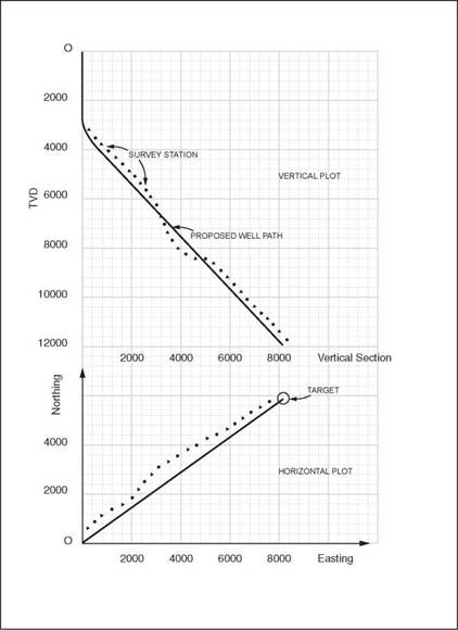
When drilling a directional well, the actual trajectory of the well must be regularly checked to ensure that it is in agreement with the planned trajectory (Figure 1). This is done by surveying the position of the well at regular intervals. These surveys will be taken at very close intervals (30’) in the critical sections (e. g. in the build-up section) of the well. Whilst drilling the long tangential section of the well, surveys may only be required every 120′. The surveying programme will generally be specified in the drilling programme. If it is found that the well is not being drilled along its planned course, a directional orientation tool must be run to bring the well back on course. In general the earlier such problems are recognised the easier they are to be corrected. Surveying therefore plays a vital role in directional drilling.
|
|
The principles used in surveying a wellbore are the same as those used in land surveying.

