 Turbulent Flow of Newtonian Fluids in Pipes
The equation for the pressure losses in turbulent flow of a Newtonian fluid in a pipe is derived from incorporating a control factor in the pressure loss equation:
_2
Equation 13 Fanning Equation for Pressure Loss
This equation is known as the Fanning Equation and the friction factor, f defined by this equation is called the Fanning friction factor. All of the terms in this
|
|
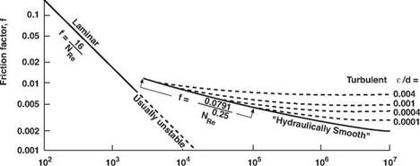
equation, except for the friction factor, can be determined from the operating parameters. The friction factor, f is a function of the Reynolds Number NRe and a term called the relative roughness, e/d. The relative roughness is defined as the ratio of absolute roughness, e, to the pipe diameter where the absolute roughness represents the average depth of pipe-wall irregularities. A plot of friction factor against Reynolds number on log-log paper is called a Fanning chart (Figure 13).
1.0
|
0.5 0.2
Figure 13 Fanning Chart for Friction Factors for Turbulent Flow in Turbulent Flow in Circular Pipes Reynolds Number, NRe |
An empirical correlation for the determination of friction factors for fully developed turbulent flow in circular pipe has been presented by Colebrook. The Colebrook function is given by:
|
|
Equation 14 Colebrook Function
The friction factor, f appears both inside and outside the log term of Colebrook’s equation and therefore an iterative technique is required to solve the equation. This difficulty can be avoided by using the graphical representation of the function. in Figure 13.
|
Equation 15 Colebrook Approximation for smooth Pipe |
For smooth pipe, the Colebrook equation reduces to:
|
|
|
ХУ: |
I
Blasius presented a straight-line approximation (on a log-log plot) of the Colebrook function for smooth pipe and a Reynolds number range of 2,100 to 100,000. This approximation is given by:
0.0791
|
N |
0.25
Re
Equation 16 Blasius modification of Colebrook Approximation
where 2,100 < NRe > 100,000 and e/d = 0.
In addition, the Fanning equation can be applied to laminar flow if the friction factor for the laminar region is defined by:
F = 16
Nr
Once it is possible to determine the value of f then the Fanning equation can be re-arranged for the calculation of frictional pressure drop due to turbulent flow in circular pipe. Re-arranging and converting to field units gives:
2
dP = fpv2 dL 25.8d
Equation 17 Pressure Loss in Turbulent Flow in Pipes
Using Equation 17, a simplified turbulent flow equation can be developed for smooth pipe and moderate Reynolds numbers:
dP = pa75qLV-25 dL d4’75
Equation 18 Pressure Loss in Smooth Pipes and Moderate Numbers
The above equation is only valid for circular pipe where e/d = 0 and NRe is between 2,100 and 100,000. Equation 18 is in a form that readily identifies the relative importance of the various hydraulic parameters on turbulent frictional pressure loss. For example, it can be shown that changing from 4.5in. to 5in. drillpipe would reduce the pressure loss in the drillpipe by about a factor of two.
