 WELLHEADS AND CASiNG HANGERS
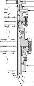
All casing strings, except for liners, are suspended from a wellhead. On a land well or offshore platform the wellhead is just below the rig floor. When drilling offshore, from a floating vessel, the wellhead is installed at the seabed. These subsea wellheads will be discussed in the chapter relating to Subsea Drilling. The wellhead on a land or platform well is made up of a series of spools, stacked up, one on top of the other (Figure 6). Surface wellhead spools have four functions:
• To suspend the weight of the casing string;
• To seal off the annulus between successive casing strings at the surface;
• To allow access to the annulus between casing strings;
• To act as an interface between the casing string and BOP stack.
When the casing string has been run into the wellbore it is hung off, or suspended, by a casing hanger, which rests on a landing shoulder inside the casing spool. Casing hangers must be designed to take the full weight of the casing, and provide a seal between the casing hanger and the spool. There are two types of surface wellhead in common use:
The procedure for installing a spool type wellhead system (Figure 6) can be outlined as follows:
(a) The conductor (30") is run and cemented in place. It is then cut off just above the ground level or the wellhead deck (on a platform);
(b) The 26” hole is drilled and the 20" casing is run through the conductor and cemented. Sometimes a landing base is welded onto the top of the 20” casing so that it can rest on the top of the 30” conductor, to transfer some weight to the 30" casing.
(c) The 20" casing is cut off just above the 30" casing and a 20" casing head housing (lowermost casing head) is threaded, or welded, onto the top of the casing. The internal profile of this housing has a landing surface on which the casing hanger of the subsequent casing string (13 3/8”) lands. The housing has two side outlets which provide access to the 20”x13 3/8” annulus. The upper flange of the housing is used as the lower part of the connection to the BOP stack used in drilling the next hole section. A ring gasket is used to seal off the connection between the housing and the BOP stack.
(d) The 171/2” hole is drilled and the 13 3/8" casing is run with the hanger landing in the 20" housing. The casing is cemented in place. The BOP stack is disconnected and a casing spool (13 5/8") is flanged up on top of the 20" housing. The BOPs are made up on top of the 13 5/8” spool and the 12 1/4" hole is drilled.
The process continues, with a new spool being installed for each casing string. Eventually a tubing head spool is installed. This spool allows the completion tubing to be suspended from the wellhead. The minimum I. D. of a casing spool must be
|
% |
greater than the drift I. D. of the previous casing. A protective sleeve known as a wear bushing is installed in each spool when it is installed and before the drillstring is run. The wear bushing must be removed before the next casing string is run.
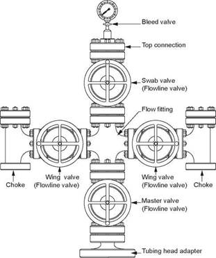
Finally the Christmas tree is installed on top of the wellhead (Figure 7). A ring gasket, approved by the API, is used to seal off the space between the flanges on the spools. The gaskets have pressure energized seals and can be rated up to 15000 psi.
The disadvantages of this type of wellhead are:
a lot of time is spent flanging up the spools;
the large number of seals, increases the chance of a pressure leak;
BOPs must be removed to install the next casing spool;
a lot of headroom is required, which may not be available in the wellhead area of an offshore platform.
|
|
|
Tubing hanger Tubing head spool Side outlet Tubing |
|
Casing hanger |
|
Side outlet Casing head spool Sealing medium Casing hanger Side outlet Casing head housing Surface casing Intermediate casing Production casing Production tubing |
|
Figure 6 API Wellhead |
|
Figure 7 Conventional Xmas Tree |
The compact spool was developed as an alternative to the conventional spool discussed above. A compact spool enables several casing strings or tubing to be suspended from a single spool. The first step in using this type of wellhead is to install the 20" casing head housing, as in the case of the spool type wellhead. after the 13 3/8” casing is run and cemented, the casing is cut off and the speedhead is connected to the casing head housing. The BOps can then be connected to the top of the housing, and the next hole section drilled.
The 9 5/8" casing is then run, with the hanger resting on a landing shoulder inside the speedhead. a 7" casing string can be run, and landed, in the speedhead in a similar manner to the 9 5/8" casing. The tubing string may also be run and landed in the speedhead. The Christmas tree can then be installed on top of the speedhead.
The disadvantage of the compact spool is that the casing programme cannot be easily altered, and so this system is less flexible than the separate spool system.
There are two types of casing hanger in common use. Wellheads can be designed to accept both types of hanger.
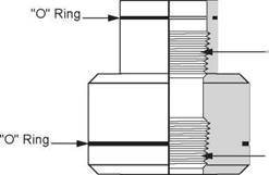
Mandrel (boll weevil) Type Casing Hangers: This type of hanger (Figure 8) is screwed onto the top of the casing string so that it lands in the casing housing when the casing shoe reaches the required depth. short lengths of casing, known as pup joints may have to be added to the string so that the casing shoe is at the correct
X
depth when the hanger lands in the wellhead. The calculation which determines the length of pup joints required to achieve this positioning is known as spacing out the string. Although this is the most common type of hanger it cannot be used if there is a risk that the casing will not reach bottom and therefore that the hanger will not land in the wellhead.
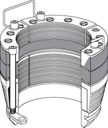
Slip Type Casing Hangers: This type of hanger (Figure 9) is wrapped around the casing and then lowered until it sits inside the casing spool. The slips are automatically set when the casing is lowered (in a similar fashion to drillpipe slips) This type of hanger can be used if the casing stands up on a ledge and cannot reach its required setting depth. These types of hanger are also used when tension has to be applied in order to avoid casing buckling when the well is brought into production.
|
|
|
.Threads |
|
.Threads |
|
Figure 8 Mandrel or Boll-Weevil type casing hanger |
|
Figure 9 slip type casing hanger |


