 Conversion and operation of a Scania truck
a) General description of the converted truck
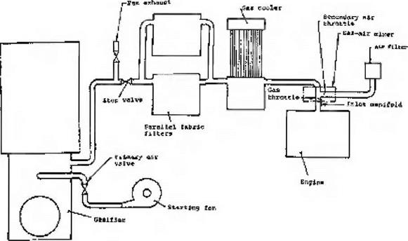
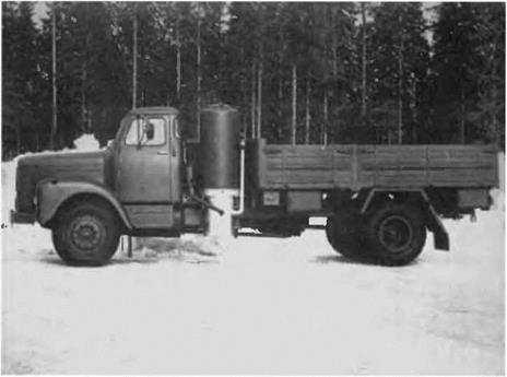
The experiences from conversion of this truck have been reported (in Swedish) by Axelsson (2). The gasifier system, which originally was the prototype design type F5, was later replaced by the mass production prototype design F500. This change was made in 1979 after approximately 45000 km. Table 3.14 gives the main data for the converted vehicle. The gasifier system is shown in Fig. 3.12, and a picture of the converted truck in Fig. 3.13.
The entire gasifier system including the gas cooler is mounted on a frame which is bolted to the chassis behind the driver’s cabin. To make space for the gasifier installation, the platform was shortened. The distance between the cabin and the platform is now 108 cm. This reduced the platform area to about 80 percent of the original.
|
|
|
Figure 3.13 Picture of a Scania L8050 truck converted to wood gas operation
|
|
Table 3.14 Specification of Scania truck converted to producer gas
1/ Tests have been done also with throat 165 mm and nozzles 14,5 mm. This gave 1% improved max. power. |
2/ Later replaced by type F500.
The injection pump is of the in-line type, and equipped with a vacuum regulator. The delivery valves have idling holes. No modifications to the injection pump were made. The damper for the regulator was adjusted to suppress tendencies for oscillations of the control rod.
The injection pump is set for dual fuel operation by moving the stop lever from the full feeding position to an adjustable stop close to the zero feed position. This gives a fuel flow below that required for idling.
Therefore it is possible to shut off the engine by moving the lever to this position when the engine is operated on straight diesel oil or by closing the gas throttle when the engine is operated with dual fuel. The lever can be operated from the driver’s cabin using the ordinary stop control. The injectors are mounted in steel sockets in the cylinder head. The steel sockets are directly surrounded by cooling water. No modifications to avoid overheating of the injectors were made since it was assumed that this would not be necessary.
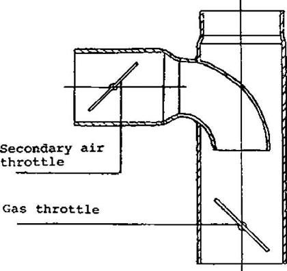
A gas/air mixer, Fig. 3.14, was connected to the inlet manifold of the engine. The gas throttle is manoeuvered by the gas pedal, the secondary air throttle by a manual control in the
driver’s cabin. The compartment between the two throttles in the secondary air line is connected to the vacuum chamber of the injection pump regulator. This makes it possible to use the regulator to limit the runaway speed of the engine. The air filter was moved to make space for the gas/air mixer. The crank case ventilation was changed to a closed system in order to avoid leakage of poisonous gas. The ventilation pipe, which originally opened to the atmosphere below the engine, is now connected to the hose between the air cleaner and the gas/air mixing valve.
The truck was tested using different compression ratios and injection timings in order to find the most suitable combination. The results of these tests are summarized in Table 3.15.
It was found that the best performance in dual fuel operation was obtained with a compression ratio reduced from 1:16.5 to 1:15.9 and injection at 35 before TDC. The reduced compression ratio was achieved by using one of the copper sheets from a cylinder head gasket as an extra spacer between the cylinder head and the engine block.
b) Laboratory performance tests
Laboratory performance tests were carried out to establish the performance with different compression ratios, injection timings, throat and air nozzle diameters and designs of the gas/air mixing valve.
 |
Control Secondary air Gas throttle
|
Figure 3.14 Gas air mixers tested for the Scania L8050 truck — b. Gas-air mixer designed by the National Testing Institute for Agricultural Machinery
|
|
Table 3.15 Experiences from tests with different compression ratios and injection timing for dual fuel operation of a Scania D8 engine
|
The conclusions from these tests have been summarized in the preceding section.
The maximum power for straight diesel operation was found to be 70.5 kW (at 2090 rpm) with the reduced compression ratio. After mounting the gas/air mixer and adjusting it, and adjustment of the injection timing to 35° before TDC, the power was reduced to 60.2 kW (at 1720 rpm). The maximum power output for dual fuel operation was found to be 49.8 kW (at 2230 rpm), i. e. 71 percent of the power for straight diesel operation at the reduced compression ratio.
The diesel oil injection was found to be about 15 percent of that for straight diesel operation,
c) Experiences from practical operation
The truck has been operated since March 1969, and has covered more than 91500 km in dual fuel operation, and 28000 km using straight diesel oil. It is still operational. The truck has been used for various types of transport, to teach drivers, for tests with different types of fuel and for demonstration.
Table 3.16 shows the fuel consumption as determined in practical operation for different loads. The diesel oil substitution is about 80 percent, compared to straight diesel operation of the truck in its converted version. The consumption of wood chips for substitution of 1 kg of diesel oil is about 3.6 kg, indicating a practical efficiency of the gasifier system of about 71 percent.
Training for dual fuel operation of a driver with earlier experience of driving a diesel truck requires only about five hours, three of them theoretical preparation, and about two of practical training. Such quickly trained drivers have used the truck on several occasions for round trips of several thousand kilometers without major problems. The drivers have, however, remarked that city driving — in particular in Stockholm — with dual fuel is much more inconvenient than highway driving. In the city, more planning was necessary to refuel in a suitable place. The large smoke clouds exhausted during fanning were considered a problem. Poor acceleration after stops at traffic lights was also found inconvenient.
During the practical testing, records were kept on fuel consumption, service and maintenance intervals, and equipment failures. A summary of these records is given in section 3.2.4.
|
Table 3.16 Fuel consumption observed in practical dual fuel or straight diesel operation of a Scania L8050 truck
1/ Average speed about 60 km/in. 2/ Wood chips 10 x 10 — 40 x 40 mm, moisture content 8 -10%. |


