 Design guidelines for downdraught gasifiers
A review of the design characteristics of the Imbert gasifier (Fig. 2.11) has been compiled on the basis of Swedish experience (43).
|
HOOD loading
|
Dimensioning of the Imbert gasifier is closely related to the "hearth load" concept. The hearth load В is defined as the amount of producer gas reduced to normal (p, T) conditions, divided by the surface area of the "throat" at the smallest circumference and is usually expressed in m3/cm2/h. Alternatively the hearth load can be expressed as the amount of dry fuel consumed, divided by the surface area of the narrowest constriction (Bs), in which case hearth load is expressed in Kg/cm2/h. Because one kilogramme of dry fuel under normal circumstances produces about 2.5 m3 of producer gas, the relation between Bg and Bs is given by:
Bg = 2.5 Bs
According to the information provided in (8) Bg may reach a maximum value of about 0.9 (Bs = 0.36) in continuous operation in good "Imbert" type gasifiers. Higher values of Bg give rise to extreme pressure drop over the reduction zone of the equipment.
Minimum values of Bg depend essentially on the heat insulation of the hot zone. Below a certain hearth load the temperature in the hot zone is lowered so much that tar production becomes inevitable.
Normal "Imbert" type generators show minimum values of Bg in the range of 0.30 — 0.35, resulting in power turn-down ratios of a factor 2.5 — 3. Modern gas producers are better insulated, and can operate tar-free at Bg values of 0.15 — 0.18.
Designing an "Imbert" type gasifier now boils down to estimating the maximum amount of gas needed. This is easily done by taking into account the cylinder volume and number of revolutions as well as the volumetric efficiency of an internal combustion engine coupled to the system (see section 2.1 and Appendix 1). From this gas amount as well as from the В maximum value (0.9) the area of the smallest constriction and the diameter of the throat can be calculated.
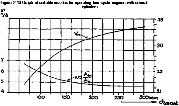
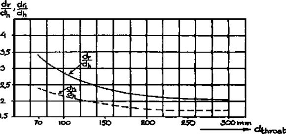
The Swedish Academy, of Engineering Sciences (43), also presents empirical data with regard to the height of the nozzles above the narrowest constriction, the diameter of nozzle opening ring as well as of suitable nozzles for different capacities.
These data are reproduced in Figures 2.12 to 2.14 and in Table 2.7.
 ^throat
Table 2.7 Suitable nozzles for wood gas generators operating with four-cycle engines (43)
|
|
 |
dt = diameter of throat at smallest cross-sectional area dn = nozzle diameter n = number of nozzles to be installed
|
Figure 2.14 Diameter of nozzle ring and nozzle opening in relation to hearth constriction, as a function of hearth diameter, for various generator makes
|
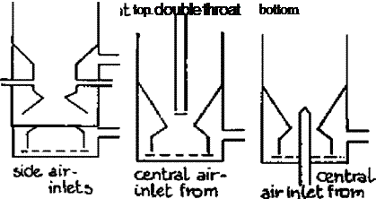
Venselaar (46) compares the design characteristics of a number of gasifiers that were commercially available during the Second World War. A distinction is made between "no throat" "single throat" and "double throat" (Imbert type) designs (see Figure 2.15). He comes to the conclusion that the three types differ mainly in maximum allowable hearth load, giving values of В max. of 0.03, 0.11 and 0.4, respectively for "no throat", "single throat" and "double throat" gasifiers.
Further conclusions from this comparison are that:
— nozzle air inlet velocities should be around 30 — 35 m/s;
— throat inclination should be around 45° — 60°;
— hearth diameter at air inlet height should be 10 cm larger than "throat" diameter in case of a "single" throat design, and about 20 cm larger than the diameter of the narrowest constriction in case of "double" throat design;
— height of the reduction zone should be more than 20 cm (the average height of reduction zone for the gasifiers reviewed was 32 cm);
— height of the air inlet nozzle plane should be 10 cm above the narrowest constriction.
As far as "double throat" or "Imbert type" gasifiers are concerned, there is good agreement between design rules presented by the authors of (43) and (46).
It must be emphasized that the above empirical design rules are based on experiences with gas producers fuelled by wood blocks varying in size between 3 to 5 x 6 to 8 cm.
A more theoretical approach is given by Groeneveld (17) who points out the importance of the fuel size. He proposes that the determining factor of the maximum load of any given gasifier is the residence time of the fuel in the pyrolysis zone. If this residence time is too short, heat penetration into a given fuel particle is insufficient to cause complete
devolatilization. Consequently further production of volatiles will occur in the reduction zone, leading to tar evolution and tar entrainment in the product gas.
Groeneveld (17) takes the time necessary for complete devolatilization to be equal to or larger than the Fourier time for heating up. By making some assumptions about the extension and geometry of the pyrolysis zone, a maximum gasifier load independent of the fuel particle size can be calculated.
Figure 2.15 Classification of down-draught gasifiers according to Venselaar (46)
 |
In comparing Groeneveld’s calculations with actually measured maximum gasifier loads, calculated loads seem to be too high by a factor of 1.5 — 2. The reasons for this discrepancy are not completely clear. Venselaar proposes a time-lag between complete heating up and complete devolatilization. Alternatively, the influence of the particle size distribution on the outcome of the maximum load calculations may have to be considered (see Appendices 1 and 2).


