 Gasifier for wood chips
Towards the end of the Second World War, gasifiers for vehicles using wood blocks as fuel had been developed to a stage where the technology appeared to be reasonably reliable. Design rules for matching the gasifier dimensions to the size and operating conditions of the engine were fairly well established. The design rules used at that time in Sweden have been summarized in (43).
The first tests with wood chips reported by Nordstrom (33) in 1963 were made in a modified Imbert type downdraft gasifier with a V-hearth, see Fig. 3.1, with a fixed grate. The experiences were quite distressing. Bridging in the fuel bunker gave irregular flow of fuel in the gasifier. Clogging of the reduction zone leading to a large pressure drop of the gasifier appeared after less than one hour of operation. High tar content was observed for some tests.
It was soon concluded that a moving grate was necessary for wood chips to be used as fuel. The bridging problem was found to be associated with sticking of the fuel to the wall in the pyrolysis zone where some of the tars driven off from the fuel condensed and caused a sticky surface. The problem was reduced to what was considered acceptable by the
introduction of a baffle in the fuel bunker for the purpose of eliminating contact between the fuel and the walls, in the pyrolysis zone, see Fig. 3.2.
Figure 3-1. Modified Imbert-type downdraft gasifier with V-hearth tested by Nordstrom (33)
Figure 3.2 Sketches of standard type gasifiers for wood chips and wood blocks — a.
 |
Wood chip design
|
|
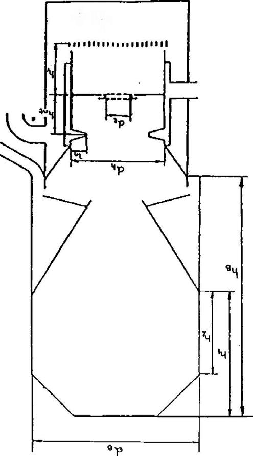
The main dimensions of the three standard sizes of gasifiers, each with four combinations of choke plate and nozzle sizes, are shown in Table 3.2 and Fig. 3.3.
In comparison with the design guidelines for wood block gasifiers presented in Chapter 2, the maximum "hearth load" В defined as the superficial velocity of gas through the narrowest section of the gasifier is generally slightly higher, i. e. about 1.0 m /cm h., and the turn-down ratio higher, i. e. about 6-9. The dimensions of the standard designs for wood chip gasifiers show the following differences from the recommendations in Chapter 2.
— The number of air nozzles is generally larger.
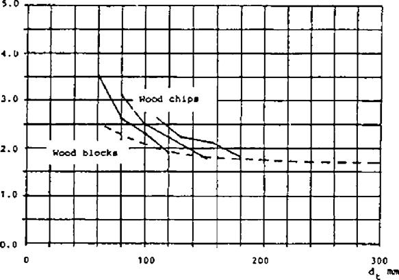
— The ratio of the nozzle area to the throat area varies in somewhat different ways for the three standard sizes of the firebox, see Fig. 3.4.a.
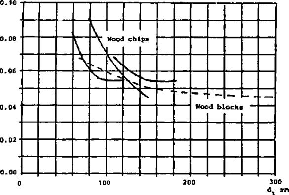
— The ratio of the firebox diameter to the throat diameter d/d is generally higher than recommended for wood blocks.
— The ratio of the nozzle tip diameter to the throat diameter d t/d is generally greater than recommended for wood blocks.
— The height of the reduction zone is much less than the average of 32 cm for wood block gasifiers and for the smallest sizes even below the minimum height of 20 cm recommended in Chapter 2 for wood blocks.
Other features of the standard gasifiers for wood chips are that the gas is brought out of the gasifier at about the throat level and that the outer surface of the upper part of the gasifier acts as a cooling surface for condensation of water and tars. The condensate is drained into a separate vessel located close to the gasifier.
The main advent-age of this system is that it is possible to drain-off condensates which form after shut-down of the operation when the gasifier cools off. The condensate may otherwise wet the charcoal bed in the fire-zone and cause difficulties to re-ignite the gasifier. There will also be some drying of the fuel as indicated by tests reported by Nordstrom (33). According to these, 60 — 80 percent of the moisture in the wood fed into the gasifier can be drained off from the condensate jacket.
|
Table 3.2 Main dimensions of standard type gasifiers for wood chips
|
|
Dimensions of the fuel container (mm) |
|||
|
jdB |
627 627 |
627 |
720 |
|
790 930 |
1270 |
1450 |
|
|
-hi |
.340 .480 |
О CM CO |
CO о о |
|
h2 |
220 ,360 |
700 |
610 |
|
total volume dm3 |
155 199 |
o CO |
401 |
type FI
tvw I
f typg F7 f
Figure 3.3 Main dimensions of standard type gasifiers for wood chips
|
|

Figure 3.4 Design guidelines for down-draft gasifiers — a. Ratio between nozzle flow
area, An, and throat area, At, as a function of the throat diameter.
|
t
Figure 3.4 Design guidelines for down-draft gasifiers — b. Diameter of the fire box, dr, as a function of the throat diameter, dt. |
|
Figure 3.4 Design guidelines for down-draft gasifiers — c. Nozzle tip ring diameter, dnt, as a function of the throat diameter, dt. |
|

 |
The throat section is built-up by a loose throat ring resting on a support ring which can be placed at different levels below the nozzle tip plane by variation of the number of distance rings between the support ring and the brackets welded to the fire-box wall. This throat ring can easily be changed to adapt the gasifier to new operating conditions, and it can also easily be replaced if damaged by overheating.
The overall cold gas efficiency of this type of gasifier defined as: where
г) g = overall cold gas efficiency
qVg = gas volume flow
qMf = fuel mass flow
Hig = lower gas heating value
Hif = lower fuel heating value
has been determined as about 70 percent over a load range from 100 per cent to 20 percent. The tar content of the gas has been determined between 0.04 and 0.20 g/m3 over the practical load range. The tar content can be compared with the guidelines given by Tiedema et al (42) according to which the tar content should be less than 0.5 g/m3 if the gas is to be suitable as fuel for an internal combustion engine.


